


11
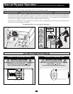
Manual Bypass Operation
(for power module maintenance or replacement)
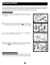
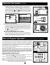
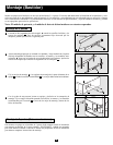
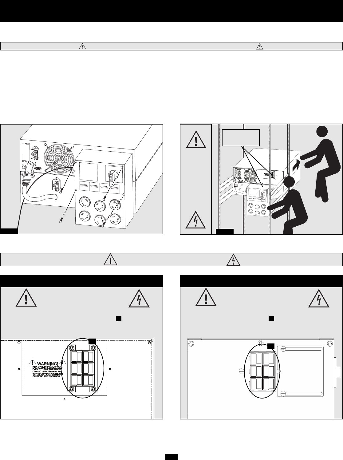
STEP 5: Remove the four screws that hold the detachable PDU to the power/battery module.
STEP 6: Using several assistants at each end, carefully pull the detachable PDU away from the power/battery module. During this process,
ensure that each section is properly supported after they are separated. If the sections are detached in a rackmount application,
ensure that each section remains adequately supported by the UPS's rackmount rails. Remove the rackmounting hardware from
the front panel of the UPS; slide the power and battery modules forward, and remove. If it is desired to leave the detached PDU
in the rack, a user-supplied crosspiece or shelf must be installed in the rear of the rack.
If the sections are detached in a tower application, ensure that the PDU is supported by the UPS's tower feet. Adjust the tower
feet so they are as close together as possible.
To reattach the PDU, reverse the process listed above.
WARNING! High Voltage! Risk of electrical shock! SEE BELOW.
Step 5
Step 6
WARNING!
High
Voltage!
Risk of
electrical
shock!
SEE
BELOW.
See Warning
Statements
below!
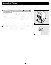
High Voltage Warnings
Contacts on Power/Battery Module
WARNING! High Voltage!
Risk of electrical shock!
Due to the presence of high voltage internal batteries, even
without AC present, these contacts are live!
Do not let these contacts touch any surface!
A
Contacts on Detachable PDU
WARNING! High voltage!
Risk of electrical shock!
If AC is present and Bypass Switch is set to “Bypass”,
these contacts are live!
Do not let these contacts touch any surface!
B
A
B