


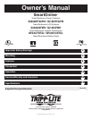
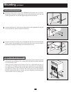
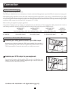
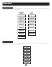

Mount the shelved sections (A) of your UPSRMRII kit on the back side of your rack.
Mount them in the lowest available space of your rack with with the screws, nuts and
washers provided (B). Note that the support ledges should face inward.
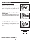
Attach mounting ears (C) to the front mounting holes of your equipment (D) using the
screws provided (E). The ears should face backward.
Using an assistant if necessary, lift your equipment and slide it onto the mounting
shelves. Attach your equipment to the rack by passing the screws, nuts and washers
provided (F) through its mounting ears and into the rack rails.
5
1
2
3
A
D
C
F
B
E
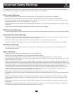
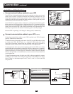
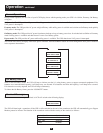
2-Post (Telecom) Installation
1
2
Mounting
continued
3
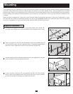
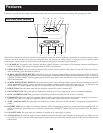
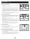
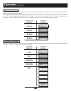
Suggested Tower Mount Installation
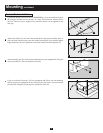
The UPS system is shipped with two sets of plastic feet (A) and extensions (B) that
can be used to tower mount the UPS, a battery pack, and either an isolation transformer
or a second battery pack.
Adjust the feet to a width of 10.25 inches (26 cm) for a UPS and battery pack, or
to a width of 15.375 inches (39 cm) for three units. Align the feet in your installation
area, approximately 10 inches (26 cm) apart. Have one or more assistants help you
place the units on their sides in the feet. The control panel of the UPS should be
the UPS’s upper corner and face outward. If you are installing a transformer, place
it between the UPS and its battery pack.
1
1
A
B