


9
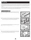
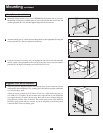
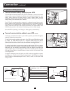
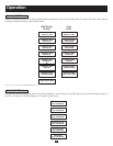
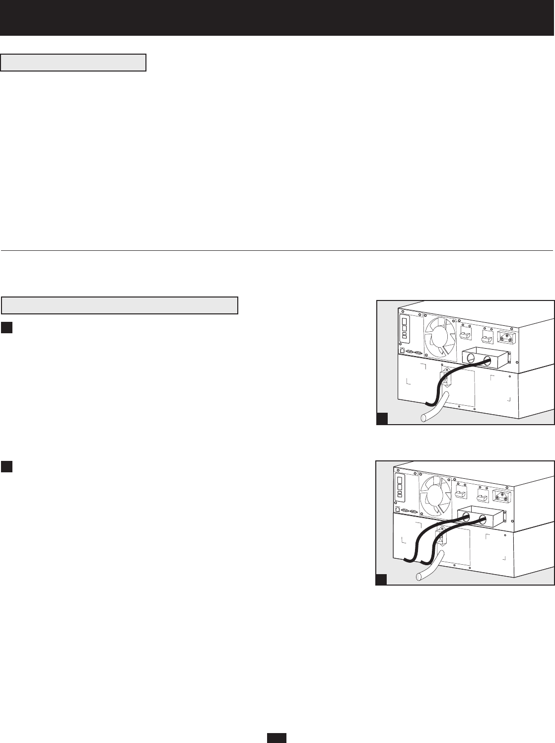
Hardwire your utility power source to your UPS’s input.
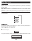
Remove the top of the box covering the UPS’s power terminals. Pass one end of a
power cable through the UPS’s cover box’s right knockout, then connect it to the
UPS’s input terminals. Connect the other end to your utility power source.
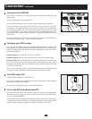
Hardwire your UPS’s output to your equipment.
Pass one end of a power cable through the UPS cover box’s left knockout, then
connect it to the UPS’s output terminals. Replace the top of the UPS cover box.
Connect the cable’s other end to your load.
Continue with Installation—All Applications (pg. 10)
1
2
1
2
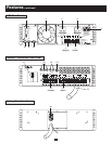
Connection
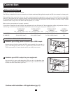
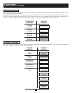
Wiring must be done by a qualified electrician.
The UPS may be installed on its own or connected to an isolation transformer. Both applications require the UPS to be connected to a battery pack.
When making wiring connections, observe the cable connection regulations appropriate to your area [e.g. National Electrical Code (NEC)
in the U.S.] at all times. Be sure to install an easily accessible disconnect switch in your installation wiring so you may cut off the UPS’s
AC input during fires and other emergencies. Ensure that cables are fitted with cable sleeves and are secured by connector clamps. Tighten
connections with a torque of not less than 24-28 inch-pounds (2.7-3.2 NM).
Make sure that your equipment is properly grounded.
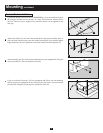
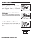
Using cables of improper size may damage your equipment and cause fire hazards. Choose appropriate cabling and protection circuits to
make wiring connections (Ground conductors must be the same size and type as the power conductors used):
RATED INPUT RATED OUTPUT RATED OUTPUT OUTPUT
CURRENT CURRENT CURRENT PROTECTION
200 - 240 (1Ø, 2-Wire + PE) 200 - 240V (1Ø, 2-Wire + PE) 120V (1Ø, 2-Wire + PE) CIRCUIT
SU6000RT3U 30A 8 AWG (10mm
2
) 30A 8 AWG (10mm
2
) 2 × 30A 8 AWG (10mm
2
) 30A
SU10KRT3U 50A 6 AWG (16mm
2
) 50A 6 AWG (16mm
2
) 2 × 50A 6 AWG (16mm
2
) 63A
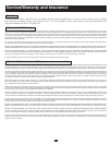
Installation—No Isolation Transformer
Notes on Hardwiring