


8
Features
continued
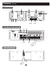
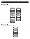
UPS Rear Panel
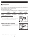
1. Output Terminal Block: Use these terminals to connect your UPS to your equipment or to the transformer’s UPS Connector. Unscrew
and remove the cover plate above the block for access.
2. Input Terminal Block: Use these terminals to connect your UPS to your utility power outlet or to the transformer’s UPS Connector.
Unscrew and remove the cover plate above the block for access.
3. External Battery Connector: Use this to connect one or more Tripp Lite Battery Packs to the UPS. Remove the cover plate for access.
The UPS will not operate without a connection to a charged battery pack. Refer to the Battery Pack owner’s manual for connection
instructions and safety warnings.
4. AC Input Breaker: One double-pole circuit breaker controls input power to the UPS.
5. AC Output Breaker: One double-pole circuit breaker controls output power from the UPS.
6. Exhaust Fan: This cools and ventilates the inside of the UPS.
7. Accessory Slot: Remove the small cover panel to install optional accessories to remotely control and monitor your UPS. Visit
Tripp Lite on the Web (www.tripplite.com) to learn about available SNMP, network management and connectivity products that may
be installed in this slot.
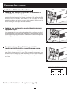
8. EPO (Emergency Power OFF) Port: This RJ11 modular jack can be connected to a user-supplied switch to enable remote emergency
shutdown. See Step 5 in “Connection,” pg. 10, for details.
9. RS-232 Communication Port: This female DB9 serial port may be used to connect your UPS to a workstation or server. It uses RS-232
protocol to communicate with a connected computer. It is used with Tripp Lite software and the included serial cable to monitor and
manage the UPS remotely over a network and to automatically save open files and shut down equipment during a blackout. See
“Connection,” pg. 10, for details.
10. Dry Contact Interface Port: This female DB9 port sends contact-closure signals to indicate line-fail and low-battery status. See
“Connection,” pg. 10, for details.
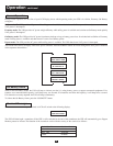
Isolation Transformer Rear Panel
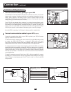
11. Utility Input Terminal Block: Use these terminals to connect your transformer to utility power. Unscrew and remove the cover plate
above the block for access.
12. Equipment Output Terminal Block: Use these terminals to connect your equipment to the transformer. Unscrew and remove the
cover plate above the block for access.
13. UPS Connector: Connect your transformer to the UPS’s Input Terminal Block by running the wires through this UPS Connector.
14 Overtemperature Reset Breaker: This circuit breaker trips if the unit’s temperature climbs too high.
15. AC to UPS Breaker: One double-pole circuit breaker controls the transformer’s power output to the UPS.
16. Output Breaker: One triple-pole circuit breaker controls the transformer’s power output to connected equipment.
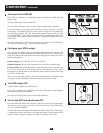
17. Manual Bypass Switch: This red and yellow dial is used to circumvent the UPS while still supporting connected equipment when
performing UPS maintenance or switching battery packs. While this switch is on BYPASS, the UPS will charge the batteries and con-
nected equipment will receive filtered AC mains power, but the equipment will not receive battery power in the event of a blackout.
Before performing UPS maintenance or switching battery packs, turn this switch to BYPASS and the AC to UPS breaker off, then shut
down the UPS and disconnect it from the transformer (disconnection is not necessary when switching batteries). Since equipment will
not receive battery power in the event of a blackout if this switch is on BYPASS, you may want to swap in a second UPS if the first
requires lengthy service.
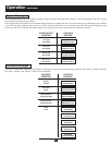
Battery Pack Rear Panel
18. Input Connector: Use this cable to daisy chain additional Battery Packs onto the first. Remove the cover panel for access. Refer to
the Battery Pack owner’s manual for connection instructions and safety warnings.
19. Output Cable: Use this cable to connect the Battery Pack to the UPS. The UPS will not operate without a connection to a charged
battery pack. Refer to the Battery Pack owner’s manual for connection instructions and safety warnings.