


54
These connections are optional. Your UPS will function properly without these connections.
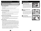
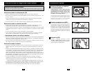
USB Communications
Use the included USB cable to connect the USB
port of your computer to the USB port of your
UPS. Install on your computer the Tripp Lite
PowerAlert Software appropriate to your computer’s
operating system. Your UPS may feature additional
communications ports; these ports may also be
connected to additional computers which have
PowerAlert Software installed. Consult your
PowerAlert manual for more information.
RS-232 Serial Communications
If your computer is equipped with a DB9 serial
port, use the included serial cable to connect the
DB9 port of your computer to the DB9 port of
your UPS. Install on your computer the Tripp Lite
PowerAlert Software appropriate to your computer’s
operating system. Your UPS may feature additional
communications ports; these ports may also be
connected to additional computers which have
PowerAlert Software installed. Consult your
PowerAlert manual for more information.
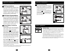
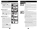
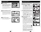
External Battery Connection
(select models)
Your UPS comes with a robust internal battery
system; external batteries are only needed to
extend runtime. Adding external batteries will
increase recharge time as well as runtime.
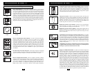
The illustration (see ) shows the location of your
UPS’s External Battery Connector, where you will
insert the battery pack cable. Complete installation
instructions for your battery pack appear in the battery
pack’s owner’s manual. Make sure that cables are
fully inserted into their connectors. Small sparks
may result during battery connection; this is normal.
Do not connect or disconnect battery packs when
the UPS is running on battery power.
If you connect an
y external batteries, set the
Battery Charge Level Switch (see ) to the up
position. This will increase your UPS’s charger
output so the additional batteries charge faster.
Note: the switch to the right of the Battery Charge
Level Switch is inactive and will not affect UPS
operation regardless of its position.
CAUTION! DO NOT set the Battery Charge Level Switch to the up position without an external battery con-
nected. There is a risk of damaging the UPS’s internal battery system.
3b
3a
3
2
1
Optional Installation
1
2
3a
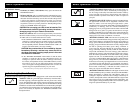
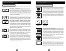
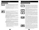
EPO Port Connection
This optional feature is only for those applications
which require connection to a facility’s
Emergency Power Off (EPO) circuit. When the UPS
is connected to this circuit, it enables emergency
shutdown of the UPS's inverter.
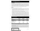
Using the cable provided, connect the EPO port of
your UPS (see ) to a user-supplied normally
closed or normally open switch according to the
circuit diagram (see ). The EPO port is not a
phone line surge suppressor; do not connect a
phone line to this port.
4b
4a
4
Optional Installation
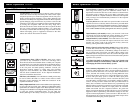
OPTION 1: USER SUPPLIED NORMALLY CLOSED SWITCH
OPTION 2: USER SUPPLIED NORMALLY OPEN SWITCH
RJ11
PLUG
5
4
3
2
NO CONNECTION
4-5 JUMPER
N.C. EPO SWITCH
RJ11
PLUG
5
4
3
2
NO CONNECTION
N.O. EPO SWITCH
3b
4a
4b
Basic Operation
Buttons
“POWER” Button
• To turn the UPS ON: with the UPS plugged into a live AC wall outlet,*
press and hold the POWER button for one second.** Release the button.
If utility power is absent, you can “cold-start” the UPS (i.e.: turn it
ON and supply power for a limited time from its batteries***) by
pressing and holding the POWER button for one second.**
• To turn the UPS OFF: with the UPS ON and receiving utility power,
press and hold the POWER button for one second.** Then unplug the
UPS from the wall outlet. The UPS will be completely OFF.
* After you plug the UPS into a live AC outlet, the UPS will automatically charge its batteries,
but will not supply power to its outlets until it is turned ON. ** The alarm will beep once
briefly after the indicated interval has passed. *** If fully charged.