


3
INSTALLATION
Your PD9000 family of pole displays has been pre-assembled to
make the installation as simple as possible.
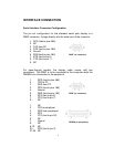
Serial Interface Non-pass-thru Models Installation
1. Mount the pole display to the metal base plate using the
mounting hardware provided.
2. The pole display can be used in a freestanding mode or
attached to the counter using the remaining mounting
hardware.
3. Connect the round DIN6M connector from the pole display to
the round DIN6F connector of the interface cable.
4. Connect the DB9F connector to the computer’s serial COM1 or
COM2 port.
5. Connect the female phone jack of the power adapter to the
male phone jack of the interface cable.
6. Plug the power adapter into a 120VAC outlet.
7. A start up text message (LOGIC CONTROLS POS
COMPONENTS) will be present for a short time. When this
message disappears the cursor will be displayed at the left-
most digit of the top row.
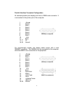
Parallel Interface Non-pass-thru Models Installation
1. Mount the pole display to the metal base plate using the
mounting hardware provided.
2. The pole display can be used in a freestanding mode or
attached to the counter using the remaining mounting
hardware.
3. Connect the DB25M connector to the computer’s parallel
printer port (LPT1).
4. Connect the female phone jack of the power adapter to the
male phone jack of the pole display cable.
5. Plug the power adapter into a 120VAC outlet.
6. A start up text message (LOGIC CONTROLS POS
COMPONENTS) will be present for a short time. When this
message disappears the cursor will be displayed at the left-
most digit of the top row.