


4
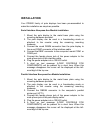
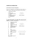
Serial Interface Pass-thru Models Installation
1 Mount the pole display to the metal base plate using the
mounting hardware provided.
2 The pole display can be used in a freestanding mode or
attached to the counter using the remaining mounting
hardware.
3 Connect the DB25M connector to the peripheral device or a
serial pass-thru terminator (optional accessory). Turn on power
of the peripheral device.
4 Connect the DB9F connector to the computer’s serial COM1 or
COM2 port.
5 Connect the female phone jack of the power adapter to the
male phone jack of the pole display cable.
6 Plug the power adapter into a 120VAC outlet.
7 A start up text message (LOGIC CONTROLS POS
COMPONENTS) will be present for a short time. When this
message disappears the cursor will be displayed at the left-
most digit of the top row.
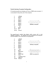
Parallel Interface Pass-thru Models Installation
1 Mount the pole display to the metal base plate using the
mounting hardware provided.
2 The pole display can be used in a freestanding mode or
attached to the counter using the remaining mounting
hardware.
3 Connect the DB25F connector to the peripheral device or
parallel pass-thru terminator (optional accessory). Turn on
power of the peripheral device.
4 Connect the DB25M connector to the computer’s parallel
printer port (LPT1).
5 Connect the female phone jack of the power adapter to the
male phone jack at the DB25M/DB25F connector.
6 Plug the power adapter into a 120VAC outlet.
7 A start up text message (LOGIC CONTROLS POS
COMPONENTS) will be present for a short time. When this
message disappears the cursor will be displayed at the left-
most digit of the top row.