Hardware Description
This Section describes the hardware of the Pro-Switch/8F and gives a
physical and functional overview of its features.
The Front Panel
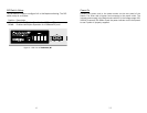
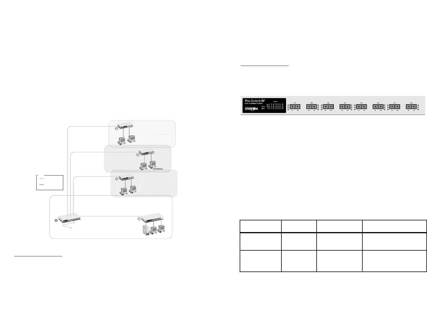
The front panel consists of (8) fiber ports, DIP switches, and LED
Indicators.
Figure 1. Front Panel view of Pro-Switch/8F
Ports
The 100Base-FX ports are capable of accepting 100Base-FX
connections only.
When connected to a 100Base-FX network, the ports operate at
100Mbps in half-duplex mode and 200Mbps in full-duplex mode.
The maximum range of an FX fiber link between a switch and another
device is up to 2 Km. using Multi-mode, 62.5/125µ fiber-optic cable or
up to 75 Kilometers using Single, 10/125-µ fiber optic cable.
The following table summarizes the port and cable specifications for
this switch.
5
Network Application
This section provides a few samples of network topology in which the
Switch is used. The Pro-Switch/8F is designed to be used as a backbone
switch. With its large address table (4000 MAC address), Fiber ports, and
high performance, it is ideal for connecting WANS to LAN network
segments.
You can use the Pro-Switch/8F to connect multiple floors of a building or
even multiple buildings via the fiber optic ports. The switch automatically
learns node addresses, which are subsequently used to filter and forward
all traffic based on the destination address. The distance between two
switches via fiber cable can be up to 2 km (Multi-Mode) or 15 km (Single
Mode).
Segment Bridge
For enterprise networks where large data broadcasts are constantly
processed, this switch is an ideal backbone solution.
12
Floor
2
oor
2
Floor
1
Floor
3
oor
3
Floor
4
oor
4
or
Legend
Category 5/5e UTP
100m
Fiber Optic Cable
Multi-Mode, 2km
Workstations
Work
s
tation
s
Work
s
tation
s
Fiber In (mm)
Server
Figure 6.
Inter-building
Application
Speed Connector Port Speed Cable
100BASE-FX Straight-tip 100/200 Mbps 62.5/125 micron
(ST or SC) fiber-optic cable
100BASE-FX Straight-tip 100/200 Mbps 10/125 micron
(SC ) fiber-optic cable


