


Installation • 17
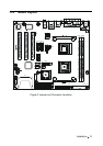
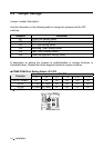
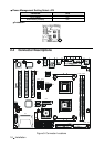
Table for Connector’s Location Description:
Use the information in the following table to change the connector.
Connectors Functions
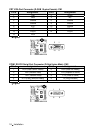
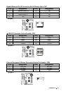
CN1 CRT VGA Port Connector
CN2 COM1 RS-232 Serial Port Connector
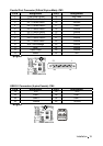
CN3 Parallel Port Connector
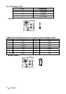
CN4 USB 0/1 Connectors
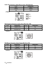
CN5 Audio Port Connector (Optional)
CN6 PS/2 Keyboard & Mouse Connectors
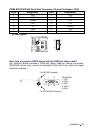
CN7 Gigabit Ethernet RJ-45 & USB 2/3 Connectors
CN8 External Keyboard & Mouse Connector
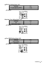
CN9 CD-IN Connector
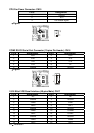
CN13 COM3 RS-232/422/485 Serial Port Connectors
CN14 COM4 RS-232/422/485 Serial Port Connectors
CN15 CPU Fan Power Connector
CN16 COM2 RS-232 Serial Port Connector
CN17 18/24 Bits LVDS Panel Interface
CN18 System Fan Power Connector
CN19 USB 4/5 (Pin-Header) Connector
CN20 System Panel Indicate Connector
CN21 Secondary IDE Connector
CN22 ATX Power Connector
CN23 Primary IDE Connector
CN24 Floppy Disk Connector
CN25 LINE OUT Connector
JP7 LAN LED Connector
SATA1 S-ATA1 Connector
SATA2 S-ATA2 Connector
CF II Type II CompactFlash™ Connector