2
INSTALLATION
NOTE: The telephone system referred to in this
manual is the customer premise equipment such
as an electronic key system, a PABX or a dedicated
single line telephone(s). The VIP-800 is not in-
tended for direct or indirect connection to the
public telephone network or to PABX analog
station ports. When used with a customer premise
telephone system such as a key system or PABX
system, these units are interfaced to the system via
a fully protected page port or system central office
port, which is a fully protected interface device.
Also, the host system must be configured to
disallow central office trunk conferencing in order
to prevent indirect connection to the public net-
work.
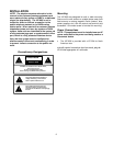
Precautionary Designations
Mounting
The VIP-800 was designed for wall or table mounting.
Secure unit to wall studs or a suitable brace away from
heat sources or strong magnetic fields (motors, fans,
power supplies, etc.) with the control and terminal strip
accessible. One wood screw is included for mounting.
Power Connections
NOTE: This equipment must be installed near an AC
power outlet due to the power cord being used as a
disconnect device.
• The VIP-800 is provided with a VP-324 for North
American use.
After all required connections have been made, plug the
VP-324 into appropriate AC wall outlet.
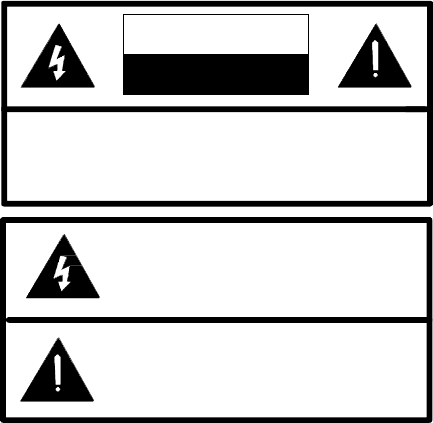
CAUTION: To reduce the risk of electric shock,
Do not remove cover.
No user serviceable parts inside.
Refer servicing to qualified service personnel.
CAUTION
RISK OF ELECTRIC SHOCK
DO NOT OPEN
This symbol indicates that dangerous
voltage constituting a risk of electric
shock is present within this unit.
This symbol indicates that there are
important operating and maintenance
instructions in the literature accompanying
this unit.


