


Aluminum Mobile Rack 3-7
10. Replace the computer’s cover and reconnect the power and other external
cabling.
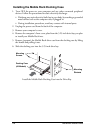
7. Position the docking case so its mounting holes align with the drive bay’s
mounting holes. Secure with the supplied mounting screws (two/four on
each side.)
8.
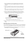
Attach an existing IDE 40-pin data cable from the system motherboard (or
IDE controller card) to the 40-pin connectors on the back of the docking
case.
Most connectors are keyed for proper insertion. If there is no key, orient the
cable so the pin-1 colored stripe edge is closest to the power connector.
9. Connect an available 4-pin power cable from the system’s power supply to
the 4-pin connector on the back of the docking case. e power connector is
‘D’ shaped to ensure proper orientation when making the connection.
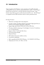
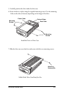
Docking
Module Data Cable and Power Connectors
40-pin IDE Connector,
Power
Connector
Pin 1
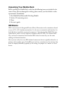
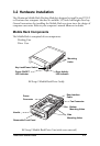
Mounting a Drive in the Drive Case
Proceed with the following steps to install a 3.5-inch drive device in the Mobile Rack
drive case. (Note: a special adapter kit is required in order to install a 2.5-inch drive.)
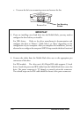
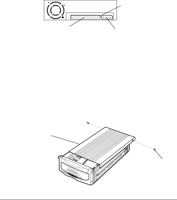
1.Remove the Mobile Rack drive case cover by removing the two mounting screws,
then sliding the cover towards the back of the unit.
Remove the Drive Case Cover
Slide Cover Off
Mounting
Screws
(x2)