


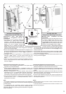
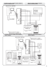
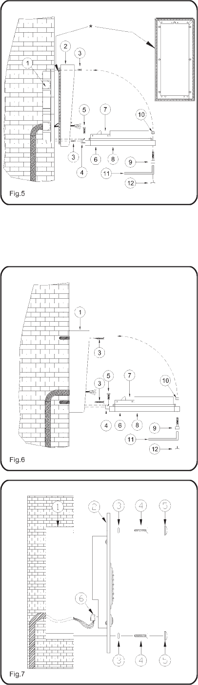
Montaggiodaincasso (Fig.5)
(Art.VK6N, VK6NMV, CVK6N, VKC6N,
VKX6N)
!
!
!
!
!
!
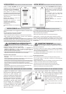
Murare la scatola da incasso (1) lasciando
dal bordo superiore a terra, 165-170cm
comemostratoinfigura4(pagina3).
Accertarsicheiforidifissaggiopresentinella
scatola da incasso siano ben puliti (in caso
contrarioprovvedereallaloropulizia).
Montare sulla scatola da incasso il tettuccio
antipioggia (2) utilizzando le 4 viti in
dotazione(3)comemostratoinfigura5.
Inserire la cerniera (4) del gruppo “supporto
unità di ripresa” (8) nell’apposita sede della
scatoladaincassoefissarlatramitele2vitiin
dotazione
Applicare del silicone sulla superficie
posteriore del tettuccio, prima di fissarlo alla
scatola da incasso, per sigillare la scatola
controeventualiinfiltrazionid’acqua.
(5).
Passare al collaudo e test dell’impianto
prima di completare il montaggio del posto
esterno.
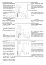
ruotare il supporto (8) verso l’alto e fissarlo
allascatoladaincasso,utilizzandolavite(9),
l’anello distanziale (10) ela chiave abrucola
(11). Ricoprire la sede della vite con il
coperchioinplastica(12)indotazione.
*IMPORTANTE!
Flushmounting(Fig.5)
(Art.VK6N, VK6NMV, CVK6N, VKC6N,
VKX6N)
!
!
!
!
!
!
Flush the back box (1) into the wall at 165-
170cmfromgroundlevel(Fig.4Page3).
If necessary clean and tidy the fixing holes
formodulesupportandothervariousholes.
Fixtherainshield(2)byusingthefourscrews
provided(3).
Insert the hinge (4) of the front support (8)
into the back box and fix it by using the two
screwsprovided(5).
Test the system and then complete the
outdoorstationmounting.
Rotate the support (8) and fix it to the back
boxwiththescrew(9),theplasticspacer(10)
and the alan key provided (11). Mask the
screw by using the plastic cover (12)
provided.
Note: to avoid water infiltrations apply silicon
sealing to the back surface of the rainshield
then fix it to the back box by using the four
screwsprovided.
*IMPORTANT!
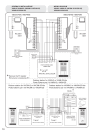
Montaggioa filomuro(Fig.6)
(Art.VK6N-S, VK6NMV-S, CVK6N-S,
VKC6N-S,VKX6N-S)
!
!
!
!
Installare a filo muro, alle quote mostrate in
la scatola di protezione
(1) utilizzando le quattro viti ad espansione
(3).
Fissare la cerniera (4) delgruppo “supporto-
unità di ripresa” (8, utilizzando le due viti in
dotazione(5).
(Fig.4 di Pagina 3),
Passare al collaudo e test dell’impianto
prima di completare il montaggio del posto
esterno.
Ruotare il supporto (8) verso l’alto efissarlo
alla scatola, utilizzando la vite (9), l’anello
distanziale (10) e la chiave a brucola (11).
Ricoprirelasede dellavite conil coperchioin
plastica(12)indotazione.
Surface mounting (Fig.6)
(Art.VK6N-S, VK6NMV-S, CVK6N-S,
VKC6N-S, VKX6N)
!
!
!
!
Fix surface box (1) to the wall at 165-170 cm
from ground level (Fig.4on Page 3) by using
thefourexpansiontypescrews(3)provided.
Fix hinge (4) of the front support (8) using the
twoscrewsprovided(5).
Test the system and then complete the
outdoorstationmounting.
Rotate the support (8) and fix it to the back
box with the screw (9), the plastic spacer (10)
and the alan key provided (11). Mask the
screwbyusingtheplasticcover(12)provided.
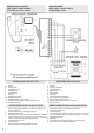
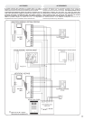
Art.VK6NBR Outdoor Station
Mounting(Fig.7)
!
!
!
!
!
!
!
For surface mounting, fix surface box to the
wall at 165-170 cm from ground level (Fig.4
on Page 3) using the four expansion type
screws provided. Continue as described
below but first fix the back box (1) to the
surfaceboxinsteadofflushingitintothewall.
Flush into the wall the back box (1) at 165-
170cmfromgroundlevel(Fig.4Page3).
If necessary clean and tidy the fixing holes
formodulesupportandothervariousholes.
Insert the connector (6) onto the front
panel(2).
Test the system and then complete the
outdoorstationmounting.
Fixthefront panel(2)intothe backbox (1)by
inserting first the 2 screw (4) into the 2
bushes (3) and then into the front panel
throughtherelevantholes.
Cover the 2 screws (4) by screwing the 2
covers(5)tothe2bushes(3).
Art.VK6NBR Montaggio del posto
esterno(Fig.7)
!
!
!
!
!
!
!
Nel caso di montaggio da superficie, fissare
(alle quote di Fig.4 Pagina 3) la scatola a
muroconle 4vitifornitea corredoed irelativi
tasselli ad espansione e procedere con i
passi successivi tenendo presente di dover
fissare la scatola da incasso (1) alla scatola
dasuperficieinvecedimurarla.
Murare la scatola da incasso (1) lasciando
dal bordo superiore a terra, 165-170cm
comemostratoinfigura4(pagina3).
Sostenendo l’unità di ripresa, passare al
collaudo e test dell’impianto prima di
completareilmontaggiodelpostoesterno.
Inserire ciascuna delle 2 viti in dotazione (4)
nelle relative boccole (3) e quindi negli
appositi fori dell’”unità di ripresa” (2) per
fissare quest’ultima alla scatola da incasso
(1).
Completare il montaggio del posto esterno
avvitando i 2 riporti “copri-boccola” ( 5) alle
2boccole(3).
Accertarsicheiforidifissaggiopresentinella
scatola da incasso siano ben puliti (in caso
contrarioprovvedereallaloropulizia).
Collegare il connettore (6) all’unitàdi ripresa
(2).
4