


030-300331 Rev. A 8 October 2002
4-Port Router (Model 2400)
User Guide
5. BEGIN THE HARDWARE INSTALLATION
This section explains the procedures for installing the Westell Router. You may choose to install the Router in one
of three ways: Ethernet only, USB only, or Ethernet and USB. To install the Router via 10/100 Base-T Ethernet
only, refer to section 5.1. To install the Router via USB only, refer to section 5.2. If you want to use both USB and
10/100 Base-T Ethernet interfaces simultaneously, please follow the procedures outlined in section 5.3.
Please wait until you have received notification from your Service Provider that your DSL line has been
activated before installing your 4-Port Router.
NOTE: If you are using a Westell Router in conjunction with an Ethernet Hub or Switch, refer to the manufacturer’s
instructions for proper installation and configuration. Westell recommends the use of a surge protector to protect
equipment attached to the AC power supply.
5.1 Router Installation via 10/100 Base-T Ethernet
You can choose to connect your primary computer via Ethernet or USB installation. Westell recommends that you
connect your Router using an Ethernet connection.
NOTE: Before you connect the Router via 10/100 Base-T, you must have an available Ethernet card
installed in your computer. If your Ethernet card does not auto-negotiate, you must set it to half duplex.
Refer to the Ethernet card manufacturer’s instructions for installing and configuring your Ethernet card. If
you do not have an Ethernet card installed in your computer but do have an available USB Port, go to the
Router Installation via USB section of this User Guide.
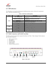
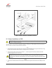
1. Connect the power supply cord to the power connector
marked
12V
on the rear panel of the Router. Plug
the other end of the power supply cord into a surge-protected AC wall socket.
2. Connect the DSL phone cable from the DSL jack
on the rear panel of the Router to the DSL-equipped
telephone jack on the wall.
WARNING: The connection to the Router’s DSL jack must come from a non-filtered connection to the
telephone jack on the wall. If you are using a microfilter, then be certain that the DSL phone cable is
connected to the “DSL/HPN” non-filtered jack. You must use the phone cord that was provided with the
Router kit.
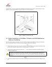
3. Connect the Ethernet cable from the Ethernet jack on the rear panel of the Router to the Ethernet port on
your computer. Repeat this step to connect up to 3 additional PCs to the Router.
NOTE: You may connect to any of the four Ethernet jacks on the rear panel of the Router as they serve as an
Ethernet hub.
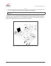
Congratulations! You have completed the Ethernet hardware installation for your Router. No USB driver software
installation is required when using an Ethernet connection. Refer to your Internet Service Provider’s instructions for
installing subscriber software and connecting to the Internet.
!
!