


030-300331 Rev. A 6 October 2002
4-Port Router (Model 2400)
User Guide
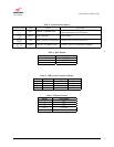
4.4 LED Indicators
The LED indicators are located on the front panel of the Router and are used to verify the unit’s operation and
status. LED states are described in Table 1.
Table 1. LED States and Descriptions
LED State Description
Slow Flashing Green
Power ON and waiting for carrier detect signal
(1 flash/sec)
Moderate Flashing Green
Power ON and attempting synchronization
(2 flashes/sec)
Solid Green
Power ON and synchronized with ADSL line card
Steady Red (less than 20 sec.)
Hardware power-up in process
Flashing Yellow
Modem failed self-diagnostics
Solid Yellow
Modem is in safe boot mode
SYNC
No Light
No Power
Solid Green
USB link established
Flashing Green
Transmit or Receive Activity
USB
No Light
No USB link established
Solid Green
Ethernet link established
Flashing Green
Transmit or Receive Activity
Ethernet
Ports
1,2,3,4
No Light
No Ethernet link established
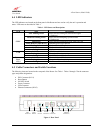
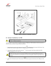
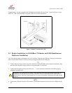
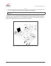
4.5 Cable Connectors and Switch Locations
The following items are located on the rear panel of the Router. See Table 1. Tables 2 through 5 list the connector
types and pinout designations.
• DSL Connector (RJ-11)
• Reset Button
• ON/OFF Switch
• Power Connector
• USB Connector
• Ethernet Connectors (RJ-45)
Figure 1. Rear Panel
12V 2
1
3
4
DSL
Connector
Power
Connector
Ethernet
Connectors
USB
Connector
Reset
Button
ON/OFF
Switch