


3-1
3. Quick Start
This Quick Start Guide describes a simplified installation procedure for the
NBB-1600-D20, NBB-1600E-D20 and NBB-1600CE-D16 Network
Boot Bars, which will allow you to communicate with the unit in order to
demonstrate basic features and check for proper operation. In order to take
full advantage of the complete range of features offered by this unit, it is
recommended to complete the remainder of this User's Guide after performing
the Quick Start Procedure.
3.1. Hardware Installation
3.1.1. Apply Power to the NBB
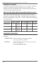
Refer to power rating nameplate on the NBB, and then connect the unit to an
appropriate power source. Note that the NBB features two separate AC inputs
and two separate power busses; connect power cables to the Circuit "A" and
Circuit "B" Power Inlets, install the cable keepers as described in Section 4.1,
then connect the cables to your power source. Refer to the table below for
information concerning power requirements and maximum loads.
Model Number
Total
Outlets
Input
Voltage
Max. Load
per Outlet
Max. Load
per Bus
Max. Load
per Unit
NBB-1600-D20 16 100 to
120 VAC
15 Amps 20 Amps 40 Amps
NBB-1600E-D20 16 100 to
240 VAC
15 Amps 20 Amps 40 Amps
NBB-1600CE-D16 16 100 to
240 VAC
10 Amps 16 Amps 32 Amps
Set the Main Power Switch in the ON position; the ON LED should light, and
the RDY LED should begin to flash. This indicates that the NBB is ready to
receive commands.