


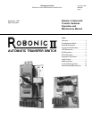
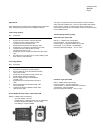
Instruction Leaflet
30-471 (E)
Page 12
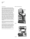
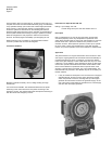
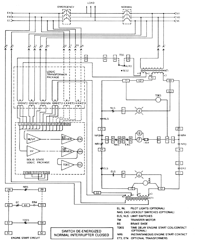
Consider the Robonic II in the normal operating position, with normal
power available and the normal interrupter closed. The following are
energized: U.V. (undervoltage module), TDES (time delay engine
start), and NR (normal relay).
The U.V. monitoring all 3 phases of the normal power, senses a dip or
loss of voltage which instantly causes NR to deenergize. Contacts NR2
and NR4 open, and contacts NR1 and NR3 close. TDES times out,
closing it’s contacts and initiating the emergency system start up. When
the emergency system reaches correct levels of voltage and frequency,
ER is energized and contact ER2 closes. This completes the emergency
control circuit, and TM (transfer motor) begins to operate.
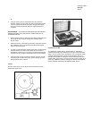
First, the normal interrupter is opened, and then the emergency
interrupter is closed. At this point, the ELS (emergency limit switch)
contacts change state, and the BS (motor brake) closes, preventing
TM over travel. The NLS (normal limit switch) contacts change state in
preparation for re-transfer to the normal power source.
Upon return of stabilized normal power, NR is re-energized disabling
the emergency control circuit, and enabling normal control circuit. The
TM operates, opening the emergency interrupter and closing the
normal interrupter. When the re-transfer is completed, the NLS contacts
change state isolating TM, and BS closes. TDES becomes energized
opening it’s contacts. TDEC times out to allow the emergency generator
to run unloaded and cool off before shutting down. The Robonic II is
now ready to react to another normal power failure.
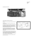
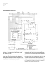
Schematic of Robonic II Transfer Switch