Instruction Leaflet
30-471 (E)
Page 4
General Description
CSA Standard C22.2 No. 178-1978 defines an automatic transfer
switch as, “self acting equipment for transferring one or more load
conductor connections from one power source to another.” The same
Standard also gives definitions for type A and type B automatic transfer
switches. “Transfer” switch type A means an automatic transfer switch
that does not employ integral overcurrent devices.” “Transfer switch,
type B means an automatic transfer switch that (does) employ integral
overcurrent protection”. Westinghouse Robonics in type A are
equipped with special instantaneous magnetic only interrupter. The trip
settings of these special interrupter are set (and fixed) at higher than
standard values. They are intended to trip only if the upstream
protective device fails to clear a fault. Incorporating these special
magnetic only interrupter, a type A Robonic operates in exactly the
same way as a transfer switch not having this feature. In the event that
both devices trip, the Robonics control circuitry will automatically
initiate transfer to the alternate source. The transfer operation will reset
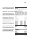
the “tripped” magnetic only interrupter. Information on instantaneous
trip value, interrupting, closing and withstand ratings, and recommen-
dations for maximum upstream protective devices for type A Robonics,
are given in tables 1, 2, 3 on page 7. The information given in these
tables is necessary for proper application. Type B “Robonics” are
equipped with standard thermal-magnetic breakers which will provide
the required overload and short circuit protection. Type B Robonics can
also be built using Seltronic or SCB breakers which could include
ground fault tripping as well as overload and short circuit protection.
For application information or assistance with type B Robonics, refer to
Westinghouse.
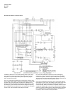
The Robonic II provides automatic transfer of an electrical load to a
stand-by power supply in the event of drop or loss of voltage of any or
all phases of the normal power supply. Upon the restoration of the
normal supply, the electrical load is automatically re-transferred to the
normal power supply.
The transfer motor utilizes the power from the source to which the
electrical load is being transferred. The mechanism is also designed to
leave both breakers trip free in the closed position, permitting incorpo-
ration of the thermal and short-circuit protection in either or both
breakers. In the higher ampacity models, type RO and PRO, an alarm
switch contact is supplied. This contact is connected in the transfer
motor circuit to lock the motor circuit out of operation when the
breaker(s) trip on an overload or short-circuit condition. Then the
breaker has to be manually reset. Instructions for the reset procedure
are located on the front of the operating mechanism.
All of the control modules are plug-in units which are easily replaced.
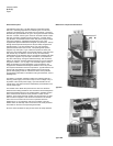
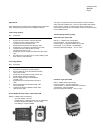
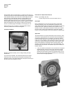
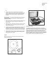
Mechanical Component Identification
Type RO
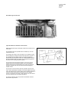
Type LRO


