FEATURES
automatically shut down. In this event, it is likely that the
draw of the equipment or appliance being operated is
greater than the battery is capable of producing.
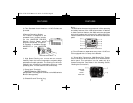
Voltage Indicator. This Bar Graph displays the voltage
being drawn from the battery by the inverter. The voltage is
measured at the Negative and Positive power input termi-
nals on the inverter. The voltage level reading will be lower
than the battery voltage due to the voltage "drop" that
occurs as the battery voltage runs through the terminal con-
nections and cables.
The inverter is designed to operate with input voltages
ranging from 10 to 15 volts. When the voltage drops below
10.5 volts DC, the voltage indicator will register in the lower
RED zone and an audible alarm will sound. If the voltage
drops below 10 volts DC, the voltage indicator will go out
and the inverter will automatically shut down.
The inverter also will shut down automatically when the
input voltage exceeds 15 volts DC. Despite this "built in"
protection, the inverter may be damaged if the input volt-
age exceeds 15 volts DC and damage caused by excess
voltage input is not covered under the WHISTLER warranty.
Under optimum conditions, the voltage reading will be in
the GREEN zone.
Note:
In the event of automatic shut down or continuous audible
alarm, turn the inverter OFF (O) until the source of the relat-
ed problem has been determined and resolved.
5
FEATURES
for safe operation. When this occurs, turn the equipment
or appliance off.
In the event of excess temperature, the High Speed
Cooling Fan also will automatically turn on. Overheating
may result when the inverter is being operated at levels
exceeding its wattage rating or because it has been
placed in a location or in an manner which prevents prop-
er heat dissipation. After approximately 15 minutes, the
High Temperature Indicator light and the Cooling Fan will
turn off and the inverter will automatically restart indicating
that the inverter temperature has dropped to a safe oper-
ating level.
c). Over Load LED Indicator Light. This light will turn RED
and the inverter will automatically shut down when the
continuous power draw from the inverter exceeds the
maximum continuous power rating for the inverter. Turn
the inverter OFF (O), determine and resolve the cause of
the overload prior to resuming operation of the equip-
ment or appliance. Turning the inverter ON (I) will reset it.
d). Battery Current & Voltage Bar Graph Meters
(GREEN, YELLOW, RED).
Current Indicator. This illuminated Bar Graph monitors
the current being drawn from the battery by the inverter.
Depending on the amount of current being drawn, the Bar
Graph reading generally will be in the GREEN or YELLOW
zone.
When the reading rises to the RED zone, the inverter may
4
1250/1750/2750 Manual 3/6/02 2:45 PM Page 7


