


3
Remote Control Switchers
680-10
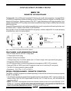
NOTE: The 680-10 should normally be plugged into an unswitched AC outlet. However, if the power to
the 680-10 is turned off by a power failure, or other means, the internal memory will retain the last selected
switched condition for each of the outlets.
INSTALLATION
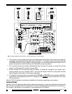
Fig. 3 illustrates an installation where a 680-10 Remote AC Switcher, along with a 599-00 Pulsed Switching
Module and a 590-00 Programmable Controller, provides the AC power management in a 4-zone system.
It allows each zone AV receiver to be turned ON and OFF from their respective remote rooms with separate
ON and OFF IR commands. This permits exclusive ON/OFF AC power switching without the need for
knowing status. It also allows the common sources to be switched ON when the first zone AV receiver is
turned on and OFF only when the last zone AV receiver is turned off. The system in Fig. 3 is configured
as follows:
1. The AC cords of the zone AV receivers are plugged into outlets #1 through #4, respectively, on the
680-10. Each AV receiver's power switch is left at the ON position.
NOTE: You must use AV receivers that remember their ON condition when their power cords are
unplugged. (Most AV receivers now have this capability).
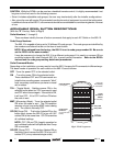
2. Outlets #1 through #4 on the 680-10 are sent separate ON and OFF commands. This means that outlet
#1 will turn ON and OFF with the ON and OFF commands from row #1 on the RC68+ Programmer.
Similarly, outlet #2 will turn ON and OFF with the ON and OFF commands from row #2 on the RC68+,
and so on. Refer to Fig. 2.
3. In order to obtain power ON/OFF DC reference signals from each zone, a 786-00 power supply is
plugged into an AC outlet (switched or un-switched) on the back of each AV receiver. These signals
are paralleled and applied to the IN+ and IN– terminals of a 599-00 Pulsed Switching Module. The 599
then passes momentary ON and OFF pulses to input ports #1 and #2 on the 590 Programmable
Controller.
4. The 590 input ports #1 and #2 are programmed with a sequence of commands. The #1 port, when
activated with an ON pulse from the 599, causes the 590 to output a sequence of IR power ON
commands for the Satellite Receiver, the VCR and the RC68+ ON command (from row #6 on the
RC68+) for outlet #6 on the 680-10.
Similarly, the #2 port, when activated with an OFF pulse from the 599, causes the 590 to output a
sequence of power OFF commands for the Satellite Receiver, the VCR and the RC68+ OFF command
for outlet #6 on the 680-10.
See the 590 instructions for programming procedures.
CAUTION: If you find that the common source equipment does not turn ON consistently (or not at all),
add a delay of approx. 1 second at the beginning of both the ON and OFF sequences in the 590. This
can be done with one or two "dummy" commands (commands that do not operate any of the functions
on the equipment in the installation).
Without the delay, the initial ON or OFF command from the handhelds (or keypads) for the 680-10 to
actuate the zone AV receivers may not have cleared the 680-10 sufficiently before the next command
(from the 590) arrives to turn on the #6 outlet for the common source equipment.
5. The IR output from the 590 (O and G) is connected to one of the zone inputs (IN and G) on the 795-
20 Zone Controller. (Any one of the zone inputs can be used for this purpose). The 590 IR signal is
then passed on to the 680-10 via one of the Common Emitter ports on the 795.
6. The common source components that can remember their ON condition when their power cords are
unplugged, are all powered from the #6 outlet on the 680-10. Those that cannot, such as the VCR and
the Satellite Receiver shown in Fig. 3, must be plugged into unswitched outlets and receive their IR
power commands from the 590 through the 795 and the common emitters.