


4
+12 VDC
IR OUT
GND
780-10
J-BOX RECEIVER
OUT
V
IR
RCVR
PWR
GS
795-20
Four Zone
Amplified
Connecting
Block
Satellite Receiver
VCR
MAIN ROOM, EQUIPMENT CABINET, ETC.
Emitter
291-10
Hidden Link™
IR Receiver
GND
+12V
ZONE 2
780-10
J-Box
IR Receiver
3-Wire
Cable
GND
+12V
480-00
Dinky Link™
IR Receiver
Red
Stripe
Smart
Pad™
GND
IR OUT
+12V
ZONE 3
CD Changer
Laser Disc
ZONE 1
AV Receiver Zone 1
490-00
Series
Micro Link™
IR Receivers
ZONE 4
3-Wire
Cable
IR OUT
GND
+12V
Red
Stripe
To 120 V AC
(u
nswitch
ed)
782-00
Power Supply
Emitter
Emitter
Emitter
AV Receiver Zone 2
AV Receiver Zone 3
COMMON
SOURCES
ZONE
RECEIVERS
3-Conductor Cable
(unshielded OK)
AV Receiver Zone 4
590-00
Programmable Controller
(back view)
786-00
Power Supply
To Zone 4
Emitter
120 V AC
(u
nswitch
ed)
To Zone 3
Emitter
To Zone 2
Emitter
To Zone 1
Emitter
1
12VDC
12VDC
1234
BANK
RES DEL SEQ PGM
+
–
234567891011 141516
OG
–+12 13
AC
Power
Strip
786-00
Unregulated
Power Supplies
plugged into an
AC outlet on
each Zone
Receiver
+
–
White
striped
side
680-10
Remote AC
Switcher
599-00
Pulsed
Switching
Module
AC for
"Power Line Switchable"
Common Sources
Zone 1 AC
Zone 2 AC
Zone 3 AC
Zone 4 AC
RESET
120 VAC
15A MAX
OUTLET 4
5A MAX
OUTLET 5
5A MAX
OUTLET 6
5A MAX
OUTLET 1
5A MAX
OUTLET 2
5A MAX
OUTLET 3
5A MAX
IR
INPUTCONFIRM
➧
TOTAL LOAD LIMITED TO 15A
Cassette DecK
To 120 V AC
(U
nswitch
ed)
7 Foot Quick
Connect Cable
CB12
Connecting
Block
Do not use
these jacks
X X
+
–
+
–
+
–
Zone 1
Emitter
Zone 2
Emitter
Zone 3
Emitter
Zone 4
Emitter
TEMPORARY POWER TAP
CAUTION: TO REDUCE THE RISK OF ELECTRIC SHOCK
USE INDOORS IN A DRY LOCATION.
680-10
REMOTE AC SWITCHER
IN+
IN–
GND
+12V
OFF
ON
GND
+12V
599-00
PULSED
SWITCHING
MODULE
283M
Blink-IR™
Mouse Emitters
IR OUT
IR OUT
COMMON
ZONE
795-20
FOUR ZONE AMPLIFIED CONNECTING BLOCK
ABABABAB+12V
ZONE 1 ZONE 2 ZONE 3 ZONE 4
IR ZONE
ZONE 4 ZONE 3 ZONE 2 ZONE 1
+12 IN G +12 IN G +12 IN G +12 IN G
POWER
10 9 8 7 6 5 4 3 2 1
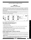
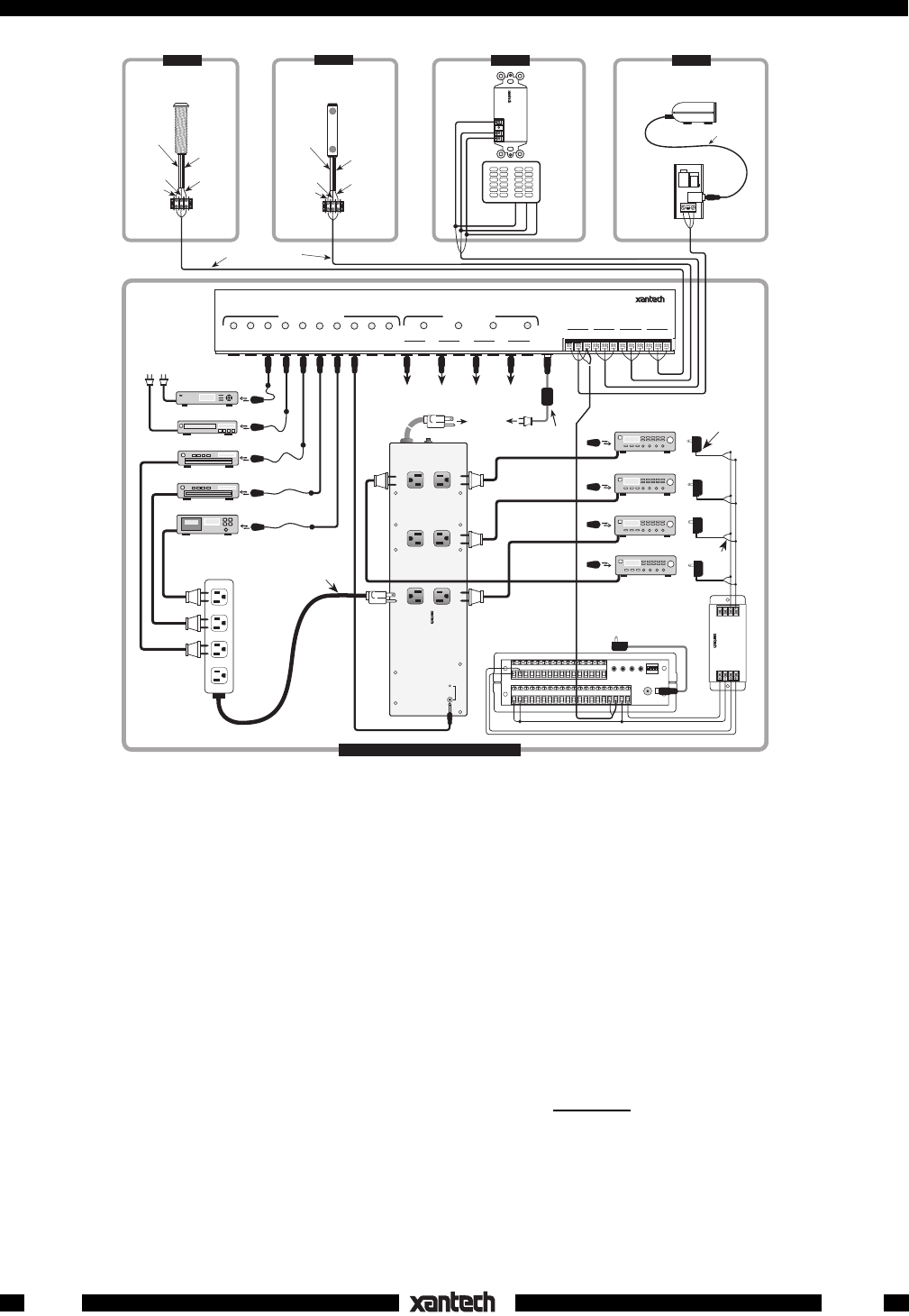
Fig. 3 A typical application of the 680-10 for AC switching in a 4-zone system.
6. The common source components that can remember their ON condition when their power cords are
unplugged, are all powered from the #6 outlet on the 680-10. Those that cannot, such as the VCR and
the Satellite Receiver shown in Fig. 3, must be plugged into unswitched outlets and receive their IR
power commands from the 590 through the 795 and the common emitters.
7. The common sources are therefore switched ON when the first AV receiver is turned ON, and will
remain on until the last AV receiver is turned OFF.
8. Finally, ON and OFF IR commands from the RC68+, for outlets #1 through #4, are "taught" into a
learning remote, such as a Xantech URC-1, and into the Xantech Smart Pad, along with all other
desired system commands, for total system operation.
9. To embellish the system further, you could add the GP-ON and GP-OFF commands from the RC68+
programmer to the keypads or the URC-1 remotes so that
all zones may be turned ON or OFF from
any zone location.
See the 795-20 Installation Instructions for additional information regarding zoned systems
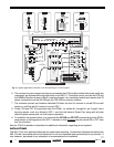
MOUNTING
The 680-10 has four attached rubber feet for stand-alone mounting. Underwriters Laboratories defines the
680-10 to be a moveable device and therefore it is not to be fastened down permanently to any surface. It
may however, be placed in any orientation to accommodate the installation.
680-10
12-20-00
Rev.C