Model MRC44CB1 Page 3
© 2002 Xantech Corporation
3. If overall distance from MRC44 Controller to secondary zone location is less than 200ft., you may power Secondary
Keypad/IR Receiver from the Primary Keypad. In this case, install a jumper across JP1 on the MRC44CB1
Connecting block.
Note: If overall distance from MRC44 to secondary zone is greater than 200ft., an external 781RG power supply
will be required. In this case REMOVE JUMPER across JP1 on MRC44CB1 and connect supply to 2.5mm coaxial
jack.
4. Properly terminate wire with RJ45 connector and connect to the connector labeled Controller on the MRC44CB1
5. Run 3-conductor wire from MRC44CB1 Connecting block location to Secondary Keypad or IR Receiver location.
6. Connect one end of the 3-conductor cable to the V G S terminals of the MRC44CB1 connecting block and the other
end to the proper +12v, IR Out, and GND terminals of the desired Keypad or IR Receiver.
Note: If IR Receiver is being connected with a 3.5mm ‘Quick Connect’ plug, simply insert plug into jack labeled IR
IN on MRC44CB1
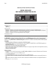
FOUR ZONE - FOUR SOURCE AUDIO/VIDEO CONTROLLER/AMPLIFIER
MRC44
1234
POWER
POWER
CH
CH
STATUS
SELECT
PLAY
STOP
PAUSE
FF
REW
VOL
VOL
MUTE
POWER
CH
CH
STATUS
SELECT
PLAY
STOP
PAUSE
FF
REW
VOL
VOL
MUTE
200 feet max (61 m)
MRC44CB1
C
IR Receiver
781RG Power Supply
PWRIR IN
CONTROLLER KEYPAD
+12V GND SIG
JP1
LED1
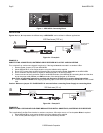
Figure 2c – Example C
EXAMPLE C
ADDING AN IR RECEIVER TO A ZONE WITH A MRC44 KEYPAD
This is applicable if the IR Receiver needs to be in a different location than the Keypad/s or if a “CFL Friendly” or “Plasma
Friendly” IR Receiver is required.
1. Mount MRC44CB1 to a convenient location using the Adhesive strip supplied
2. If only one IR Receiver is to be added, you may power this from the MRC44 Controller. In this case, place a jumper
across JP1 on the MRC44CB1 connecting block.
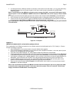
3. From the Primary MRC44 Keypad, run a CAT5 cable to where the IR Receiver will be located.
4. Properly terminate both ends of the cable with RJ45 connectors. Plug one end into the connector labeled Expansion
on the MRC44 Keypad and the other end into the connector labeled Controller on the MRC44CB1 connecting block.
5. If IR Receiver is equipped with a “quick connect” 3.5mm connector, plug directly into the jack labeled IR IN on the
MRC44CB1. If the IR Receiver has “stripped” ends, plug the appropriate wires into the V, G, and S terminals.
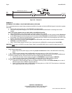
6. If another MRC44 Keypad is being used, run another CAT5 cable from the MRC44CB1 connecting block to the
location of the next keypad and properly terminate both ends with RJ45 Connectors
7. Plug one end into the connector labeled Keypad on the MRC44CB1 and the other end into the connector labeled
Controller on the MRC44 Keypad
Note: If the overall distance between the MRC44 Controller and the last Keypad in the line is greater than 200ft.,
an external power supply will be needed. In this case, remove the jumper across JP1 and use a 782-00 Power
Supply connected to the MRC44CB1 connecting block.