


Installation
2–14 973-0031-01-01 Rev A
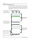
Wiring - General
The ACCB-L comes with a ground bar only. The ACCB-L-L1 is pre-wired at the
factory and ready for connection to one Sine Wave Plus Inverter/Charger. The
factory-installed wires are labeled to assist with the installation procedure.
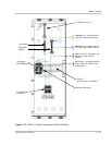
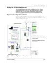
See Figure 2-12 on page 2–17 for an illustration of the ACCB-L-L1.
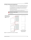
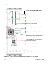
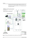
See Figure 2-13 on page 2–18 for an illustration of the ACCB-L2-PCK installed
in the ACCB-L-L1 to create the ACCB-L-L2.
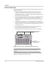
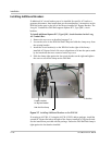
Accessing the AC Input/Output Terminal Block in the ACCB-L-L1
Consult the Sine Wave Plus Inverter/Charger Owner’s Manual for additional
information on wire and disconnect requirements.
To prepare the ACCB-L-L1 and inverter for wiring installation:
1. Expose the AC Input/Output Terminal Block in the ACCB-L-L1 by removing
the front cover, as described on page 2–6.
2. Expose the terminal block in the SW Plus Inverter by removing the AC access
cover, as described in your inverter’s owner’s guide.
WARNING: Shock Hazard
Any changes to factory wiring must meet local and national electrical codes.
WARNING: Fire Hazard
A possible fire hazard can exist if 120 Vac only sources (such as inverters and generators)
are wired incorrectly into 120/240 Vac distribution panels containing multi wire branch
circuits. For more information on multi-branch wiring, see the Xantrex website
(www.xantrex.com).
WARNING: Shock Hazard
Be sure to connect the ground wires first when connecting AC wiring to prevent a
potential shock hazard.
WARNING: Shock Hazard
While installing the components, ensure that no DC or AC voltage is being supplied to the
inverter.