Operation
3–2 973-0031-01-01 Rev A
The AC Bypass Switch
During normal operation (Figure 3-2 on page 3–3), AC power passes from the
single external AC source (generator or grid) through the inverter to the AC loads.
The inverter monitors the incoming power and uses this power to keep the
batteries charged.
When this external source of AC power is not available, the inverter switches to
external DC power (e.g., batteries, generator, solar, wind, hydro) and continues to
power the load.
When performing inverter maintenance, the breakers can be switched to the
Bypass Operation (Figure 3-3 on page 3–3) which allows the AC loads to be
powered directly from the external AC source without affecting connected AC
loads.
To de-energize both circuits, switch the breaker pair to the OFF position (Figure
3-4 on page 3–4).
Operating the AC Bypass Switch
Once the AC voltage has been applied, the bypass switch is ready for operation.
Under normal operation the Inverter Output breaker is ON.
There are three possible modes of operation for the bypass switch:
• “Normal Operation”
• “Bypass Operation”
• “AC Input/Output Off”
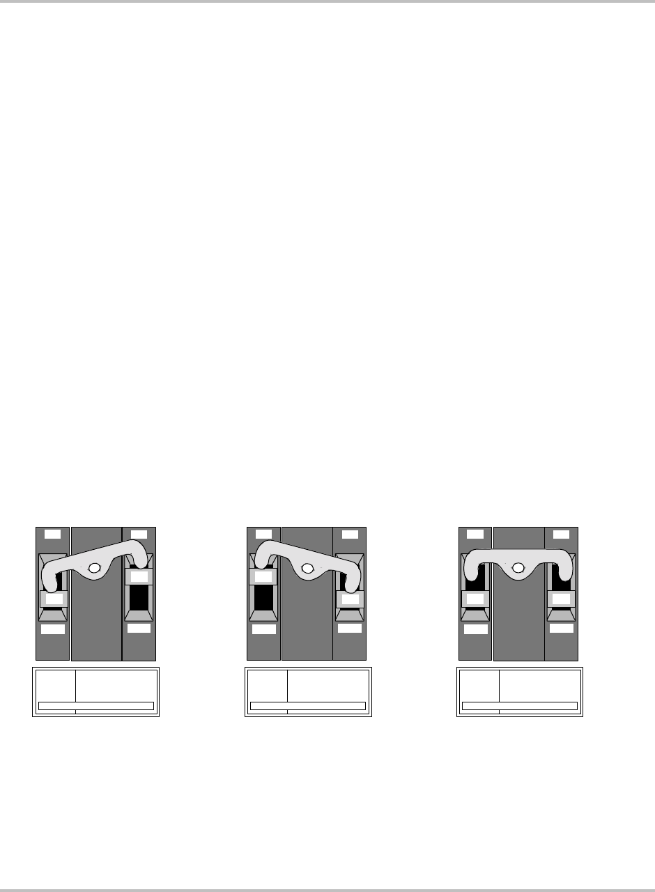
Figure 3-1
AC Bypass Switch Mode Summary
AC OFF OPERATION:
Left Breaker = OFF
Right Breaker = OFF
Utility/Generator/Inverter AC
power disconnected to Inverter
AC Distribution Panel
NORMAL OPERATION:
Left Breaker = OFF
Right Breaker = ON
Inverter AC power
available to Inverter
AC Distribution Panel
BYPASS OPERATION:
Left Breaker = ON
Right Breaker = OFF
Utility or Generator AC
power available to Inverter
AC Distribution Panel
OFF
ON
60 60
OFF
ON
OFF
ON
60
60
OFF
ON
OFF
ON
60
60
OFF
ON
BOTH OFF TO DISCONNECT AC OUTPUT
INVERTER
By pa s s 1
on to bypass
INVERTER
DISCO NNECT 1
on for normal operation
BOTH OFF TO DISCONNECT AC OUTPUT
INVERTER
Bypass 1
on to bypass
INVERTER
DISCO NNECT 1
on for normal operation
BOTH OFF TO DISCONNECT AC OUTPUT
INVERTER
Bypass 1
on to bypass
INVERTER
DISCO NNECT 1
on for normal operation


