


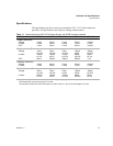
Installation and Configuration
Initial Inspection
Release 1.2 17
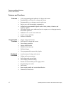
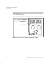
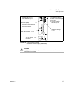
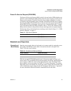
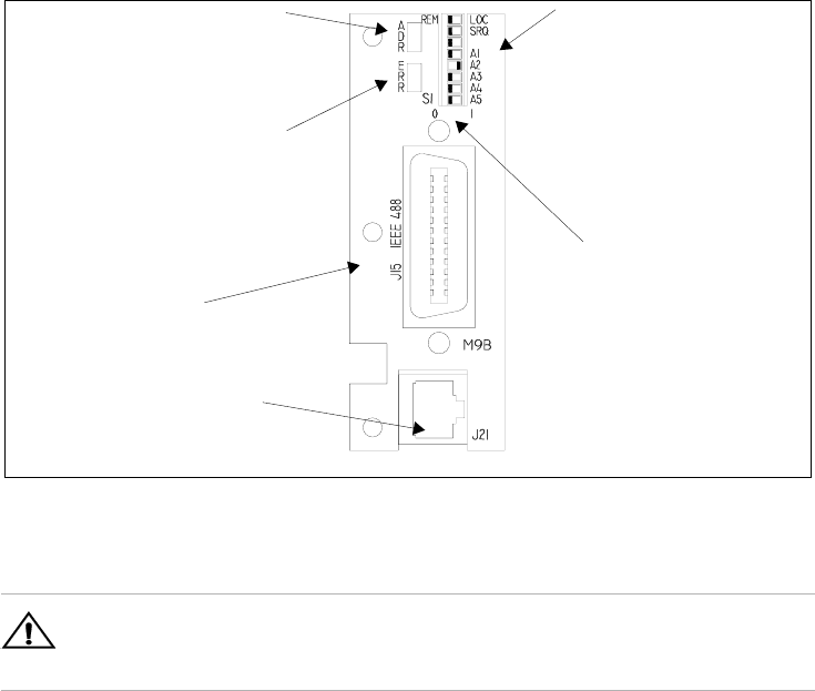
Figure 2.2 GPIB Interface Subplate
(Located on Power Supply Rear Panel)
!
CAUTION
Use proper static control techniques to avoid damage to static-sensitive components
on the printed circuit board
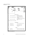
S1 Switch
1 Remote/Local Startup
2 Power On Service Reques
(Enable/Disable)
3 Not Used
4-8 Primary Address
Selection (A1-A5)
Switch Position
Reference markings
(0) (1)
Error LED (ERR)
Indicates that a programming
error has occurred. Clear with
error query command.
J21 User Signal
Connector
IEEE 488 Connector
Address LED (ADR)
Indicates that the unit is
being addressed by the
master controller.