Operation
Command Reference
42 Operating Manual for GPIB for XPD Series Power Supply
Command Description
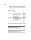
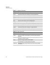
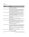
IRDAT <Ilo>,<Ihi> Calculates and records the slope and offset for readback voltage using
IRLO and IRHI data. Set CMODE ON before using this command. See also
the calibration procedures in Section 4.
<Ilo> and <Ihi> are in <current> format.
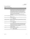
IRHI The power supply outputs a current value to an external device connected
as part of the calibration procedure and records a current readback value
internally. These values are at the high end of the programmed current
range. Refer to the output value as IRHI and record it to use as input with
the IRDAT command. Set CMODE ON before using this command. See
also the calibration procedures in Section 4.
IRLO The power supply outputs a current value to an external device connected
as part of the calibration procedure and records a current readback value
internally. These values are at the low end of the programmed current
range. Refer to the output value as IRLO and record it to use as input with
the IRDAT command. Set CMODE ON before using this command. See
also the calibration procedures in Section 4.
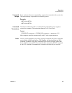
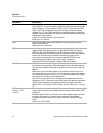
ISET <current> Sets the power supply’s output current in amps (default) or in milliamps.
This programmed current is the actual output in CC mode or the current
limit in CV mode.
Range: 0 to model maximum output current (IMAX)
Initial value: 0 amps
ISET? Asks for the supply’s present output current setting. Does not apply to
current settings which are being held. See HOLD command.
Response: ISET <current>
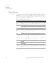
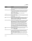
MASK <mnemonics> Disables the supply's previously unmasked operating conditions from
setting bits in the fault and status registers. See
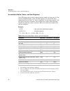
“Accumulated Status,
Status, and Fault Registers” on page 46. Mnemonics are separated from
each other by commas and may be sent in any order.
Mnemonics: CV, CC, OV, OT, SD, FOLD, ERR, PON, REM, ACF, OPF,
SNSP
Note: UNMASK NONE = MASK ALL (Initial value)
MASK NONE = UNMASK ALL
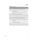
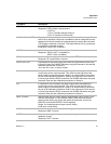
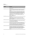
OUT <1/ON>,<0/OFF> Enables or disables the supply’s voltage/current output. The supply will
continue to accept new commands while the output is disabled but these
will not be implemented until OUT ON or OUT 1 is received. OUT ON is the
default setting. When you start the supply in remote mode, the output is
enabled.
OUT OFF (or OUT 0) also sets the isolation signal on the rear panel J21
connector, line 3. You can use the to trip external relays to isolate the power
supply from the load.
Initial value: OUT ON (or OUT 1) for output enabled
OUT? Asks for the present enabled/disabled status of the supply’s output
voltage/current.
Response: OUT 1 output enabled or
OUT 0 output disabled


