


Installation and Configuration
Communications
26 Operating Manual for RS-232 for XHR/XFR Series Power Supply
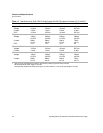
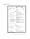
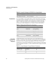
Table 2.6 Jumper/Pin Settings for DTR/DSR Flow Control (Default)
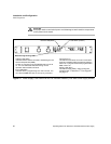
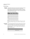
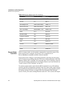
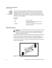
Connections Use a 9-pin (DB9) to 9-pin parallel cable to connect the interface card to the
serial port on the host computer. If you need to use a 25-pin connector (DB25)
on the host interface, ensure the correct connections are made by referring
Table 2.7. If the proper cables are not available and you need to change the
transmit/receive pin configuration, see “Transmit / Receive Pin Selection”.
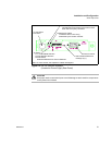
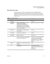
Table 2.7 Default Transmit/Receive Pin Connections
Transmit /
Receive Pin
Selection
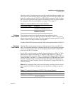
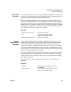
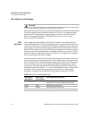
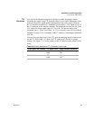
The RS-232 interface can use either pin 2 or pin 3 of the RS-232 connector to
transmit or receive data. You can set the pin orientation you want by changing
the position of the J216 jumper on the interface PCB. Table 2.8 shows the
transmit/receive pin selection on the RS-232 connector in relation to the settings
of the J216 jumper. See Figure 2.3, “RS-232 Interface PCB” on page 22 to locate
jumper J216.
Table 2.8 Jumper Settings for Transmit/Receive Pin Selection
Jumper Connections RS-232 Connector Pin
DTR (Input to RS-232)
J218 to 2-4 and 1-3
4
DSR (Output to RS-232)
J217 to 3-5 and 4-6
6
Power Supply (DCE) Host Computer (DTE)
9-pin connector
Pin 2 transmits to Pin 2 (Receive)
Pin 3 receives from Pin 3 (Transmit)
Pin 5 (Ground) connects to Pin 5 (Ground)
25-pin connector
Pin 2 transmits to Pin 3 (Receive)
Pin 3 receives from Pin 2 (Transmit)
Pin 5 (Ground) connects to Pin 7 (Ground)
Jumper J216 Connections RS-232 Connector Pin
Transmit (TXD)
4-6 (default)
4-2
3
2
Receive (RXD)
3-1 (default)
3-5
2
3