


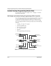

Isolated Analog Programming Mode (ISOL)
M370078-01 4-21
4
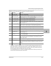
Table 4-4
AUX Output and ISOL Connector Pins and Functions J3
PIn Reference Function
J3.1 AUX_ON_OFF Auxiliary enable/disable
J3.2 COM_ISOLATED Isolated Common (Isolated from Main Output and Communication.
Return wire for +5 V, + 15 V Auxiliary Voltage.
J3.3 IS_VOL_PR_VOL Isolated Analog Voltage Programming Input
J3.4 IS_VOL_PR_CUR Isolated Analog Current Programming Input
J3.5
IS_MON_VOL
1
1.Important: Isolated monitor lines are only valid when Isolated analog programming modes are
used for the respective voltage and current control. If local control, digital control or non-iso
-
lated APG is used, the non-isolated monitor lines should be used as the isolated monitor lines
will not accurately reflect the output state of the power supply.
Isolated Voltage Monitor. Scaled to the value of the Voltage Analog
Programming Level.
J3.6 COM_ISOLATED Isolated Common (Isolated from Main Output and Communication.
Return wire for control signals, monitoring and programming.
J3.7 ISO_CUR_RES_PR Isolated Current Resistive Programming
J3.8 ISO_VOL_RES_PR Isolated Voltage Resistive Programming
J3.9
+AUX 1
2
+5 V Isolated Output
J3.10
IS_MON_CUR
1
Isolated Current Monitor. Scaled to the value of the Voltage Analog
Programming Level.
J3.11
+AUX 2
2
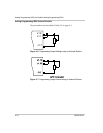
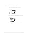
2.Use unshielded cable up to 9.84 feet (3 m) length with high-density D-Sub type connector and
a ferrite bead (Fair-Rite part number 0443164251).
+15 V Isolated Output
J3.12 SD Shutdown. Input to power supply to disable output. This input has
user selectable negative logic operation via front panel or remote
digital input/output.
J3.13 PS_GOOD PS_GOOD. Power supply output enabled.
J3.14 INTER_LOCK 1 Interlock. Dry contact type. Shorting pins J3.14 and J3.15 with the
interlock functionality enabled will disable the output of the power
supply.
J3.15 INTER_LOCK 2 Interlock