


ChipScope PLBv46 IBA (Bus Analyzer) (v1.00a)
DS619 (v1.0) September 17, 2007 www.xilinx.com
Product Specification 9
R
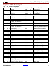
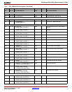
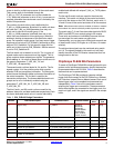
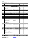
Table 2 lists the IBA PLBv46 parameterized features.
These parameters control the ports that are attached to the
IBA trigger and storage units. They also are used to
configure the storage and match unit options available for
the different trigger ports.
The IBA ports are subdivided into logical groups call match
units, as shown in Table 1, page 2. Each one of these match
units have a set of parameters which are used to enable and
define the trigger port configuration for a particular set of
PLBv46 signals.
Every match unit group has a match type and match
counter width parameter. The match unit type describes the
type of compare operation that can be done on a match
unit. The valid values for this type are defined for each
match unit. For example, C_MU_1_TYPE only supports
basic and basic with edges since multiple signals make up
this match unit. Alternately, for C_MU_3_TYPE all compare
options are available since this match unit has the complete
PLB_ABus bus connected to it. The match counter width
allows you to look for multiple occurrences of the match
event. This counter width is controllable through the
C_MU_xx_CNT_W parameter (where xx is a place holder
for the MU signal value, 1-13). When this parameter is set to
0, only one occurrence is counted; otherwise, the maximum
match event count is limited by the width of this parameter.
The number of match units is defined by the
C_MU_xx_NUM parameter. By default, if a match unit does
not have the C_MU_xx_NUM parameter, only one match
unit is used for the match unit group. If the C_MU_xx_NUM
parameter is defined, then one or two match units can be
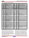
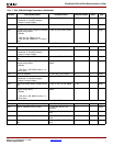
PLB Master Control Bus
G63 Use Master Control Signals C_USE_MU_11_MSTR_CTL 1,0 0 Integer
G64 Number of match units to use C_MU_11_NUM_MSTR_CTL 1,2 1 Integer
G65 0=basic, 1=basic w/ edges C_MU_11_TYPE_MSTR_CTL 0,1 0 Integer
G66 Match unit counter width. 0 means do not
use
C_MU_11_CNT_W_MSTR_
CTL
0,1-32 0 Integer
G67 1=Enable storing MU 11 signals in the data
sample storage buffer.
0=Disable
C_USE_MU_11_MSTR_CTL must be 1 in
order to store.
C_MU_11_EN_STORE_
MSTR_CTL
0,1 0 Integer
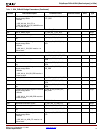
PLB Master Size and Type Status
G68 Use Master Size and Type Signals C_USE_MU_12_MSTR_SZ 1,0 0 Integer
G69 0=basic, 1=basic w/ edges C_MU_12_TYPE_MSTR_SZ 0,1 0 Integer
G70 Match unit counter width. 0 means do not
use
C_MU_12_CNT_W_MSTR_SZ 0,1-32 0 Integer
G71 1=Enable storing MU 12 signals in the data
sample storage buffer.
0=Disable
C_USE_MU_12_MSTR_SZ must be 1 in
order to store.
C_MU_12_EN_STORE_
MSTR_SZ
0,1 1 Integer
PLB Master Byte Enable
G72 Use M_BE C_USE_MU_13_MSTR_BE 1,0 0 Integer
G73 0=basic, 1=basic w/ edges C_MU_13_TYPE_MSTR_BE 0,1 0 Integer
G74 Match unit counter width. 0 means do not
use
C_MU_13_CNT_W_MSTR_BE 0,1-32 0 Integer
G75 1=Enable storing MU 13 signals in the data
sample storage buffer.
0=Disable
C_USE_MU_13_MSTR_BE must be 1 in
order to store.
C_MU_13_EN_STORE_
MSTR_BE
0,1 1 Integer
Table 2: IBA_PLBv46 Design Parameters (Continued)
Generic Feature/Description Parameter Name Allowable Values
Default
Value
VHDL
Type