


13
Notes:
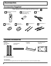
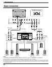
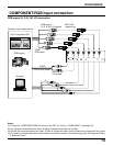
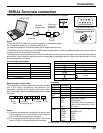
(1) Change the “COMPONENT/RGB-IN” setting in the “SET UP” menu to “COMPONENT”. (see page 34)
(2) Any equipment and cables other than the display illustrated above are not included.
(3) Choose one connecting cable from Video, S Video or Component Video, that is suitable for the equipment being used.
(4) The quality of images obtained varies between connection methods in the descending order of Component Video,
S Video and Video.
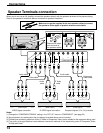
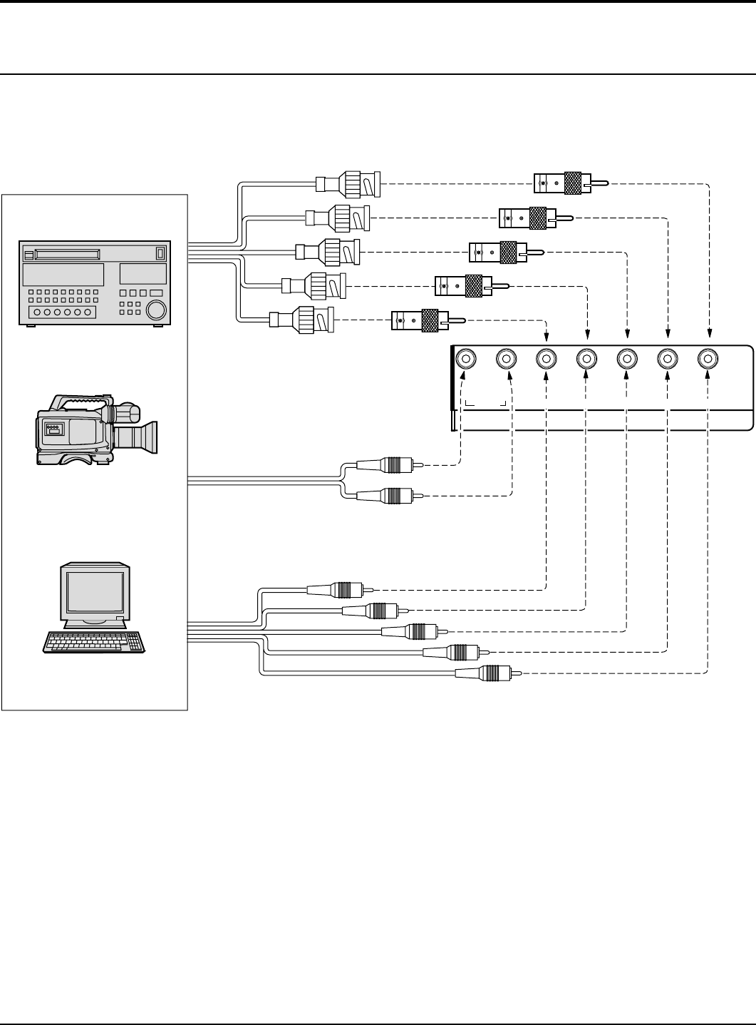
Connections
COMPONENT/RGB Input connection
COMPONENT/RGB IN
RL
AUDIO
Audio input to
L/R sockets
G
B
R
VD
HD
AUDIO
2×RCA audio cables
5×BNC
RGB cables
RGB input to
R, G, B, HD, VD sockets
BNC-RCA
adaptor plug
Example of input signal source
HDTV-compatible VCR
Computer
RGB camera
VD
HD
P
R
/C
R
/R
P
B
/C
B
/B
Y/G
RGB signal (R, G, B, HD, VD) connection