


29
ENGLISH
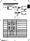
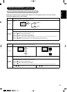
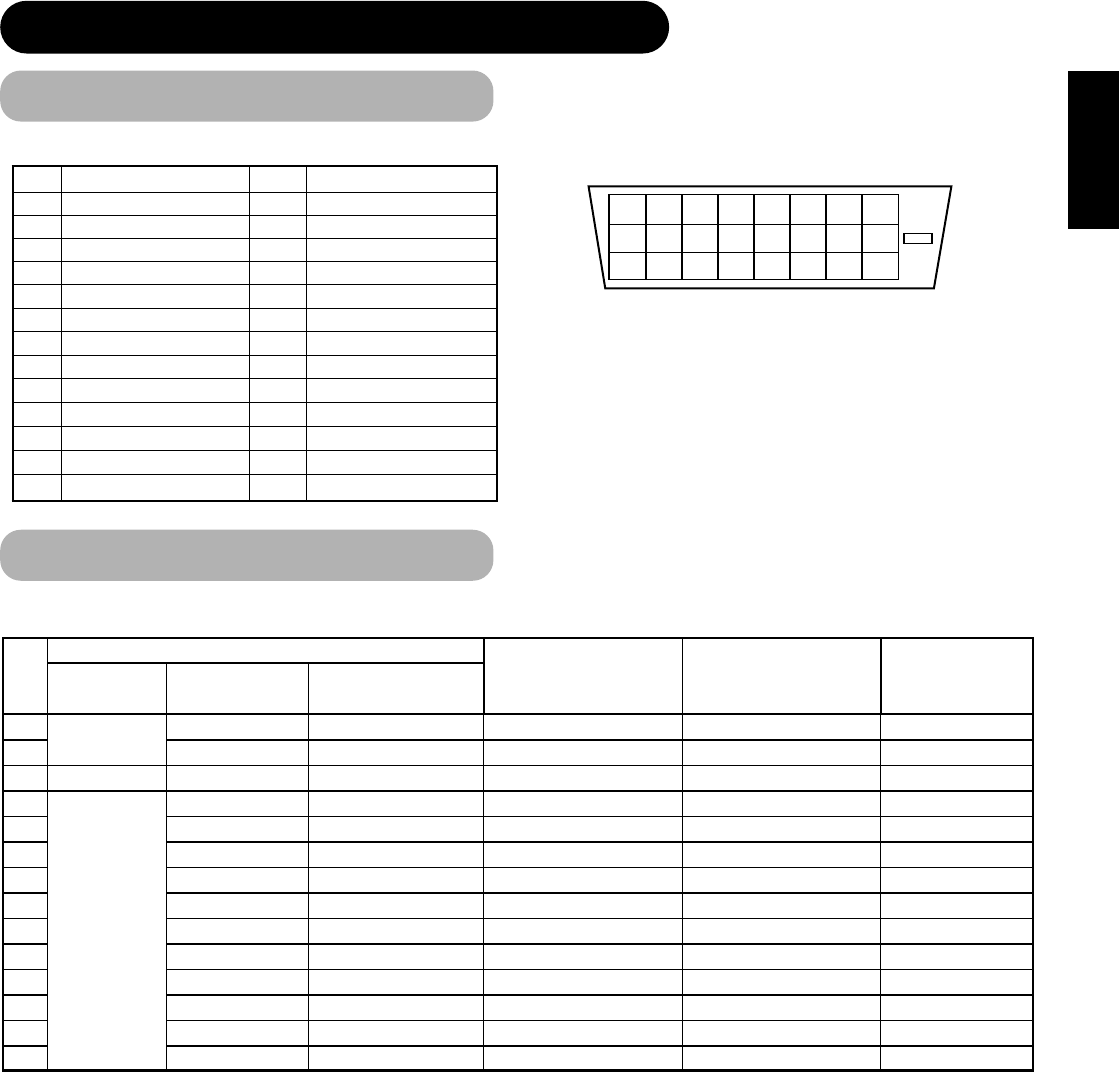
Signal Input (continued)
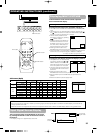
12345678
910111213141516
17 18 19 20 21 22 23 24
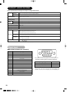
PRODUCT SPECIFICATIONS (continued)
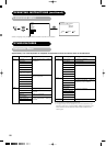
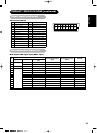
DVI terminal (DVI-D)
Pin Input signal Pin Input signal
1
T.M.D.S. Data2-
14
+5V Power
2
T.M.D.S. Data2+
15
Ground (for+5V)
3
T.M.D.S. Data2/4 Shield
16
Hot Plug Detect
4
T.M.D.S. Data4-
17
T.M.D.S. Data0-
5
T.M.D.S. Data4+
18
T.M.D.S. Data0+
6
DDC Clock
19
T.M.D.S. Data0/5 Shield
7
DDC Data
20
T.M.D.S. Data5-
8
No Connect
21
T.M.D.S. Data5+
9
T.M.D.S. Data1-
22
T.M.D.S. Clock Shield
10
T.M.D.S. Data1+
23
T.M.D.S. Clock+
11
T.M.D.S. Data1/3 Shield
24
T.M.D.S. Clock-
12
T.M.D.S. Data3-
Frame GND
13
T.M.D.S. Data3+
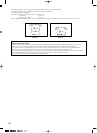
With Digital RGB signal input (RGB1 input)
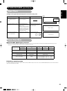
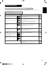
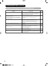
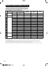
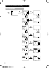
Recommended Signal List
• Make sure that the signal of the equipment to be connected is compatible with the specifications on this list.
Signal Name Resolution
Vertical frequency
(Hz)
Signal mode
No.
Horizontal frequency
(kHz)
Dot clock frequency
(MHz)
Remarks
WVGA type : On