


42
PRODUCT SPECIFICATIONS (continued)
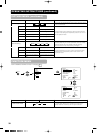
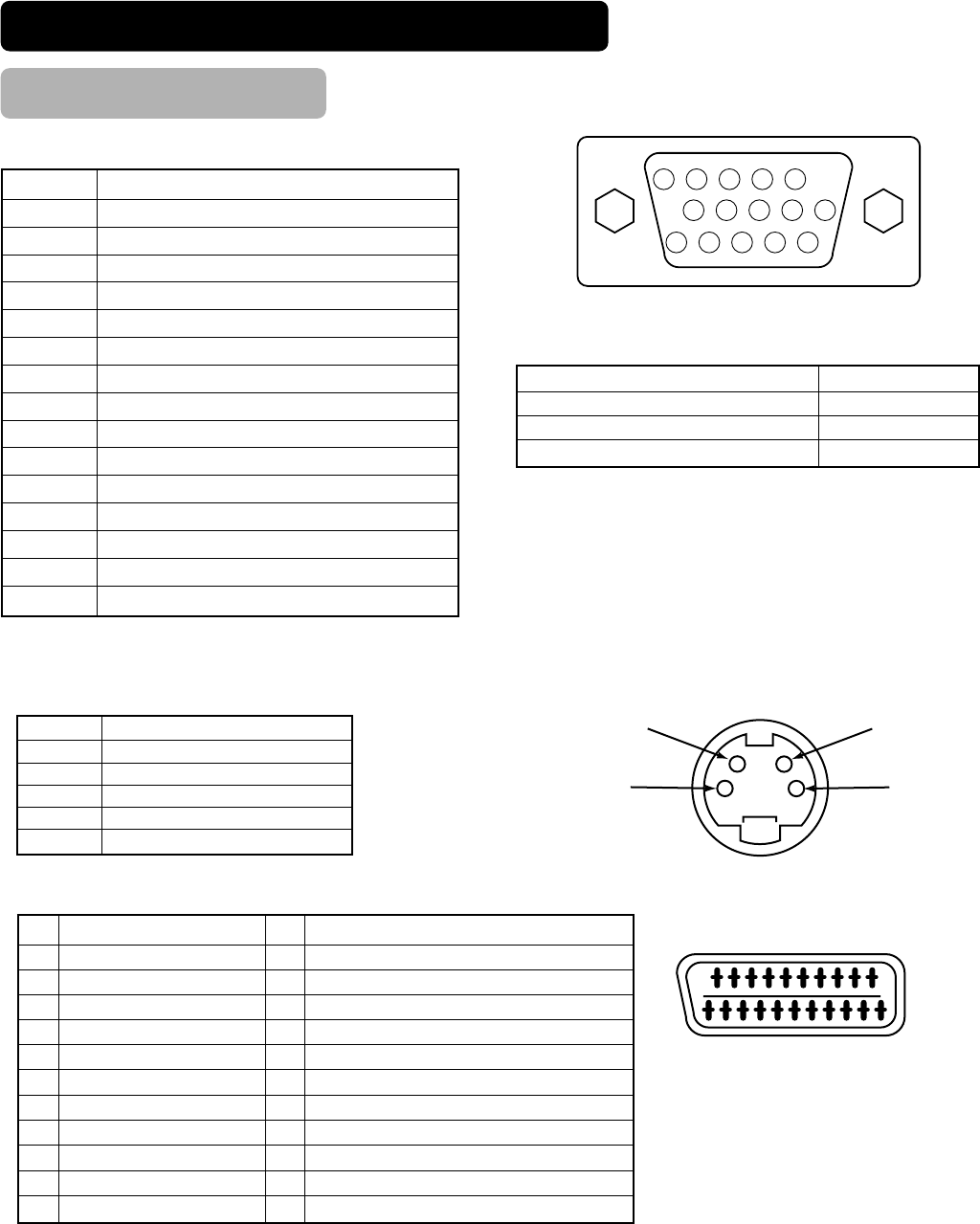
Signal Input
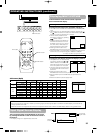
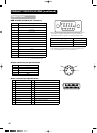
S-input connector pin specifications
Pin Input signal
1Y
2 Y-GND
3C
4 C-GND
Frame GND
20 18 16 14 12 10 8 6 4 2
21
19 17
15 13 11 9
7
5
31
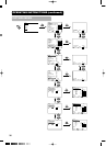
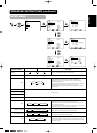
Scart connector pin specifications
Pin Signal Pin Signal
1
AUDIO OUT (RIGHT)
12
Not Used
2
AUDIO IN (RIGHT)
13
RGB-R GND
3
AUDIO OUT (LEFT/MONO)
14
GND
4
AUDIO GND
15
RGB-R / S.VHS CHROMINANCE IN
5
RGB-B GND
16
BLANKING SIGNAL
6
AUDIO IN (LEFT/MONO)
17
COMPOSITE VIDEO GND
7
RGB-B IN
18
BLANKING SIGNAL GND
8
AUDIO/RGB SWITCH / 16:9
19
COMPOSITE VIDEO OUT
9
RGB-G GND
20
COMPOSITE VIDEO / S.VHS LUMINANCE IN
10
Not Used
21
GND / SHIELD (CHASSIS)
11
RGB-G IN
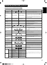
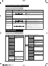
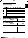
RGB terminal (D-sub 15-pin connector)
• When different kinds of input signals are simultaneously input to
the monitor via a graphics board or the like, the monitor will
automatically select the signals in the following priority order:
*There may be instances when correct display is not possible even
when displaying the signals listed on the following page. In this
case, use H/V separate sync, H/V composite sync.
Sync signal type Priority
H/V separate sync. 1
H/V composite sync. 2
sync.on Green * 3
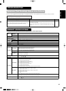
Pin
Input signal
1 R (PR/CR)
2 G or sync on green (Y)
3 B (PB/C
B)
4 No connection
5 No connection
6 R.GND (P
R/CR, GND)
7 G.GND (Y, GND)
8 B.GND (P
B/CB, GND)
9 No connection
10 GND
11 No connection
12 [SDA]
13 H. sync or H/V composite sync
14 V.sync. [V.CLK]
15 [SCL]
( ) : With component input