TNN 500AF
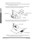
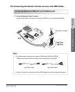
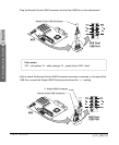
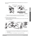
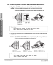
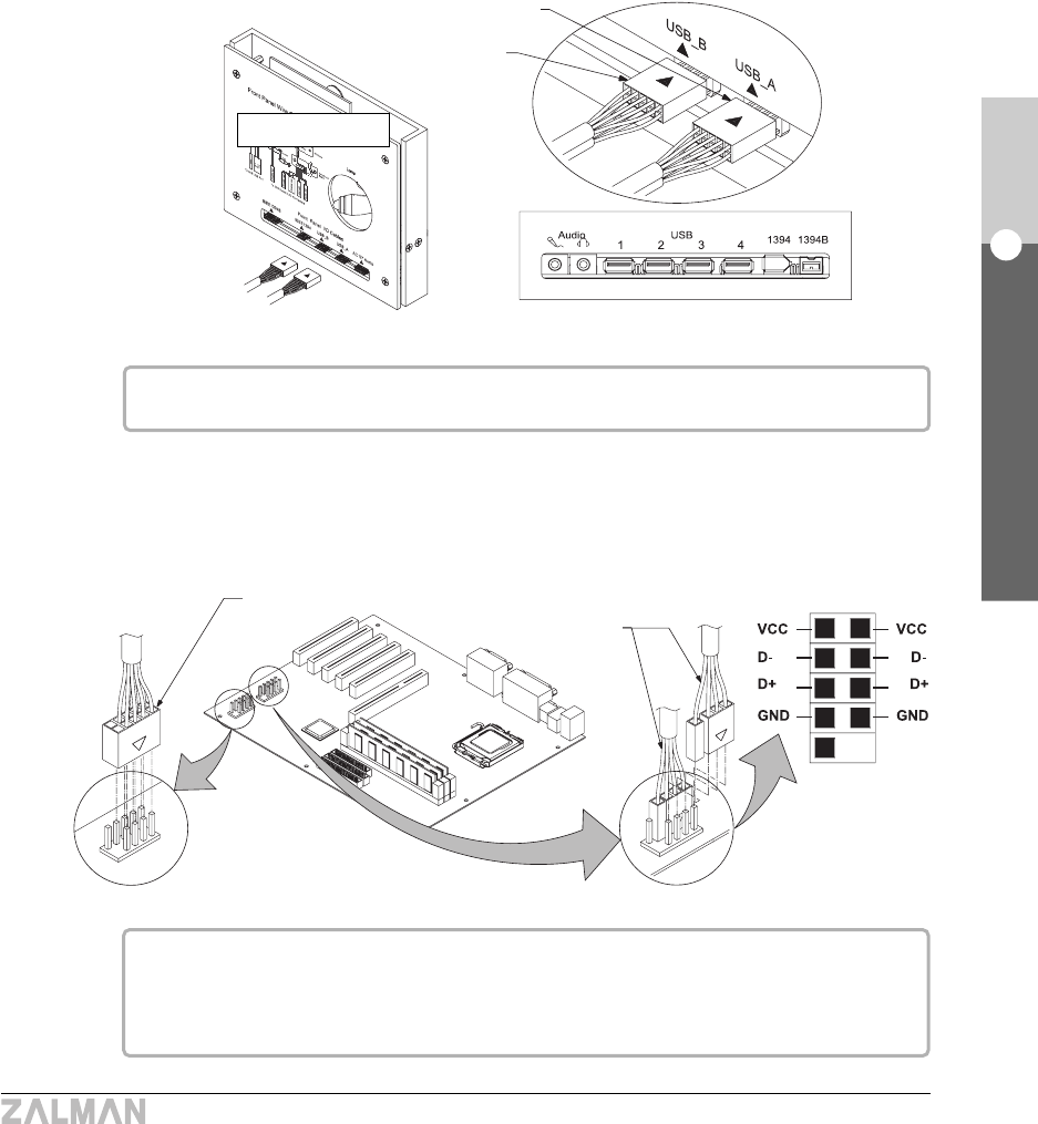
- Plug in the Dual USB-A and USB-B Connectors into their respective ports on the back of the
Switch Panel.
USB ports #1 through #3 (see diagram) can be used in this configuration.
To Sacrifice the Remote Control Function
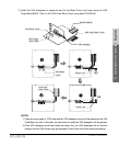
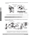
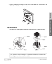
- Plug the Dual USB-A Connector and the Dual USB-B Connectors into each of the Dual USB
Ports on the motherboard.
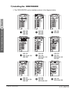
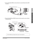
1) Verify the location and the layout of the USB headers from the motherboard manual.
2) Color codes
VCC : red (yellow), D- : white (orange), D+ : green (blue), GND : black


