


FM60-7309 Operator’s Manual
Page 10 888-249-4855 • www.ZebraSkimmers.com • Zebra Skimmers Corporation
FM60-7309 Operator’s Manual
888-249-4855 • www.ZebraSkimmers.com • Zebra Skimmers Corporation Page 11
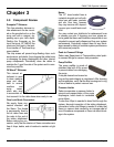
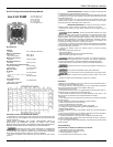
Parker Pneumatic 14E Mini Filter/Regulator
Pneumatic Division North America
Richland, Michigan 49083
14E P-RN, 8AR 14R & 15R
Manual Drain Filter Relieving Regulator
Relieving Regulator
3. Remove the bottom collar
and bowl as an integral unit.
Note: The reverse ow adapter
and element assembly should
remain in proper alignment
with the collar; they are held in
place by the o-ring between the
adapter and the collar.
4. Remove diaphragm
assembly from bonnet
assembly.
5. Remove poppet assembly,
poppet return spring, (seat)
insert and its o-rings.
6. Clean and carefully inspect
parts for wear or damage. If
replacement is necessary, use
parts from service kits.
7. Lubricate o-ring and vee
packing seals with grease found
in service kits.
8. Install poppet return spring,
poppet assembly, (seat) insert
and its o-rings.
9. Install diaphragm assembly
into bonnet assembly. Assemble
bonnet assembly to body and tighten threaded collar from 5.4 to 5.9 N•m (48 to 52
in-lbs).
10. Install bottom collar and bowl subassembly into body. Tighten collar hand tight,
plus 1/4 turn.
Safety: Polycarbonate Bowls
Bowl guards are recommended for added protection of polycarbonate bowls where
chemical attack may occur.
WARNING To avoid polycarbonate bowl rupture that can cause personal injury or property damage,
do not exceed bowl pressure of temperature ratings. Polycarbonate bowls have a 150 psig (1030 kPa)
pressure rating and a maximum temperature rating of 52°C (125°F).
MAINTENANCE 05E 06E 07E 12E
SERVICE KITS 1/8”,1/4” & 3/8” 1/4”, 3/8” & 1/2” 3/8”,1/2” & 3/4” 3/8”,1/2” & 3/4”
Element Kits
5 Micron PS902P PS702P PS802P N/A
40 Micron PS901P PS701P PS801P N/A
Grade 6 N/A N/A N/A PS884P
Grade 10 N/A N/A N/A PS885P
Relieving Regulator
Repair Kit PS908P PS71OP PS81OP PS886P
Non-Relieving
Regulator Repair Kit PS909P PS711P PS811P PS887P
EXTRA COPIES OF THESE INSTRUCTIONS ARE AVAILABLE FOR INCLUSION IN EQUIPMENT/
MAINTENANCE MANUALS THAT UTILIZE THESE PRODUCTS. CONTACT YOUR LOCAL
REPRESENTATIVE.
Introduction
Follow these instructions when installing, operating, or servicing the product.
Application Limits
These products are intended for use in general purpose compressed air systems
only Compliance with the rated pressure and temperature is necessary
Maximum Operating (Inlet) Pressure: kPa psig bar
P3A-RN, 8AR (Plastic Body) 827 120 8.3
14E (with Plastic Bowl) 1030 150 10.3
14E (with Metal Bowl) 1720 250 17.2
14R (Metal Body) 2000 300 20.0
15R (Metal Body) 1720 250 17.2
Ambient Temperature Range: O°C to 52°C (32°F to 125°F)
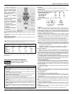
Symbols
Installation
1. This unit should be installed with reasonable accessibility for service whenever
possible - repair service kits are available. Keep pipe and tubing lengths to a
minimum with inside clean and free of dirt and chips. Pipe joint compounds should
be used sparingly and applied only to the male pipe - never into the female port. Do
not use PTFE tape to seal pipe joints - pieces have a tendency to break off and lodge
inside the unit, possibly causing malfunction.
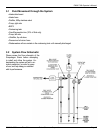
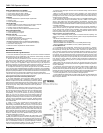
2. Install unit so that air ow is in the direction of arrow. Installation must be
upstream of and close to devices it is to service (valve, cylinder, tool etc.). Mounting
of regulators may be in any position; mounting of lter/regulators must be vertical as
shown in gure.
3. Gauge ports are located on both sides of the regulator body for your convenience.
It is necessary to install a gauge or pipe plug into each port during installation.
4. To protect regulator units against rust, pipe scale, and other foreign matter, install
a lter on the upstream (high pressure) side as close to the regulator as possible.
Caution: For proper assembly of P3A-RN and 8AR ttings, they must be installed
hand-tight and then tightened by wrench 1/2 turn. To prevent leakage past
threads, apply thread sealant to tting. Prestolok ttings are recommended. Use
of hard pipe is not recommended.
EXCESSIVE TURNING OF FITTINGS BY WRENCH MAY RESULT IN
PERMANENT DAMAGE AND RENDER THE REGULATOR INOPERABLE.
Operation of Regulator
1. Before turning on air supply, turn adjusting handle counterclockwise until
compression is released from control spring. Then turn on air supply and adjust
regulator to desired secondary pressure by turning adjusting handle clockwise. This
permits pressure to build up slowly, preventing any unexpected operation of the valve,
cylinders, tools, etc., attached to the line. Adjustment to desired secondary pressure
can be made only with primary pressure applied to the regulator,
2. To decrease regulator pressure setting, always reset from a pressure lower than
the nal setting desired. For example, lowering the secondary pressure from 550 to
410 kPa (80 to 60 psig) is best accomplished by dropping the secondary pressure to
350 kPa (50 psig), then adjusting upward to 410 kPa (60 psig).
Operation of Filter/Regulator
1. Both free moisture and solids are removed automatically by the Filter/Regulator.
2. Manual drain lters must be drained regularly before the separated moisture and
oil reaches the bottom of the element holder. Automatic drain models (pulse drain)
will collect and dump liquids automatically. They are actuated when a pressure drop
occurs within the lter.
3. The lter element should be removed and replaced when the pressure differential
across the lter is excessive.
Service
Caution: SHUT OFF AIR SUPPLY and exhaust the primary and secondary
pressure before disassembling unit. (Units may be serviced without removing
them from the air line.)
Servicing Regulator:
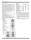
Note: See Figure 1, 2, 3 & 4 to aid with this procedure.
1. Unlock the adjusting knob by pulling upward (with the unit in an upright position.)
Then turn adjusting knob counterclockwise until compression of the control spring
has been removed.
2. Remove the bonnet from body. Then remove o-ring (7), piston, lip seal (9), and
control spring to service the bonnet subassembly. Unscrew seat (8) to service the
poppet (17), return spring (5), and/or poppet seal (6), o-rings (25 & 27), and washer
(26).
Note: On lter/regulator units, the poppet assembly & poppet return spring may be
accessed by removing lter element.
3. Clean old grease from unit and inspect seals for sign of wear (nicks, cuts, and
scratches). Repair kits are available which contain the parts which are typically
replaced.
4. Apply a light lm of grease to all seals and sliding surfaces using the grease
packet supplied with repair kit.
Note: Refer to Figures to determine the correct position and orientation of the
WARNING
To avoid unpredictable system behavior that can cause personal injury and
property damage:
• Disconnect electrical supply (when necessary) before installation, servicing, or
conversion.
• Disconnect air supply and depressurize a[ air lines connected to this product
before installation, servicing, or conversion.
• Operate within the manufacturer’s specied pressure, temperature, and other
conditions listed In these instructions.
• Medium must be moisture-free if ambient temperature is below freezing.
• Service according to procedures listed in these instructions.
• Installation, service, and conversion of these products must be performed by
knowledgeable personnel who understand how pneumatic products are to be
applied.
• After installation, servicing, or conversion, air and electrical supplies (when
necessary) should be connected and the product tested for proper function and
leakage. If audible leakage is present, or the product does not operate properly,
do not put into use.
• Warnings and specications on the product should not be covered by paint, etc.
If masking is not possible, contact your local representative for replacement
labels.