


FM60-7309 Operator’s Manual
Page 12 888-249-4855 • www.ZebraSkimmers.com • Zebra Skimmers Corporation
FM60-7309 Operator’s Manual
888-249-4855 • www.ZebraSkimmers.com • Zebra Skimmers Corporation Page 13
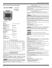
ALL-FLO Pump Service and Operating Manual
ALL-FLO PUMP
ALL-FLO Pump Co., Inc.
9321 Pineneedle Drive
Mentor, OH 44060
Ph: 440-354-1700
Fax: 440-354-9466
Email: email@all-o.com
AIR DRIVEN, DOUBLE DIAPHRAGM PUMP MANUAL
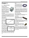
Congratulations on purchasing one of the most durable and versatile pumps made
anywhere. With the proper installation and maintenance the pump will provide years
of great performance.
READ THESE WARNINGS AND SAFETY PRECAUTIONS PRIOR TO
INSTALLATION OR OPERATION. FAILURE TO COMPLY WITH THESE
INSTRUCTIONS COULD RESULT IN PERSONAL INJURY AND OR PROPERTY
DAMAGE. RETAIN THESE INSTRUCTIONS FOR FUTURE REFERENCE.
Before placing the pump in service make certain it is compatible with
the uid being pumped. Changes of temperature, concentrations or combinations
of chemicals may vary resistance of material. Always consult Material Safety Data
Sheets and Engineering Resistance Tables for chemical compatibility.
• Be certain all operators of this equipment have been trained for safe working
practices.
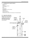
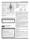
Specications
Capacity:
Adjustable 0 to 14 GPM (53,2 liters/min.)
Maximum Temperature:
KN-5 Model 200°F (93°C)
Other Plastic Models 150°F (66°C)
Maximum Air Pressure:
All Models 100 PSI (6.8 bar)
Minimum Air Pressure:
All Models 20 PSI (1.3 bar)
Dry Lift Capacity @ 100 PSI (6.8 bar):
Models w/PTFE balls 10 ft. (3 meters)
Other Models 15 ft. (4.5 meters)
Masimum Solids: 1/8” (3.2 mm)
Air Supply:
Inlet 1/4” NPT Female
• Air ow control valve supplied, 1/4” NPT or 1/2” BSP Female
Outlet 3/8” NPT Female
• Mufer supplied
Fluid Inlet/Discharge:
All Models 1/2” NPS Female
(BSP or NPT Compatible)
Performance Curve
HAZARDOUS MATERIAL: Protective eye wear and clothing should
be used whenever pumping hazardous or toxic uids.
• If a diaphragm ruptures, the pumped product can enter the air side of the pump and
exit through the air exhaust. When the uid is hazardous pipe exhaust away from the
work area and personnel.
• When the uid source is at a higher level than the pump (ooded suction), the
exhaust should be piped to a higher level than the uid source to prevent spills
caused by siphoning if a diaphragm rupture should occur.
HAZARDOUS PRESSURE: Do not clean or service pump, hoses or
dispensing valves when the system is pressurized - serious injury may result.
• Disconnect air supply line and relieve pressure from the system prior to
disassembly.
STATIC WARNING: Pumping of ammable materials may cause
a build-up of a static charge within the electrically non conductive pumps. Static
spark can cause explosion resulting in severe injury or death. Ground pump and
pumping systems when pumping ammable products or when used in a location
where surrounding atmosphere is conductive to spontaneous combustion. Optional
conductive non-metallic models are available when grounding is necessary. Use
grounding lugs and always connect to a good ground source.
• Secure pump, connections and all contact points to avoid vibrations and generation
of contact or static spark. Periodically verify continuity of electrical path to ground with
an ohmmeter from each component.
• Consult local building codes and electrical codes for specic grounding
requirements.
• Use hoses incorporating a static wire.
• Use proper ventilation
• Keep ammables away from heat, open ames and sparks.
• Keep containers closed when not in use.
Maximum temperatures are based on mechanical stress only.
Certain chemicals will signicantly reduce maximum safe operating temperature.
Consult engineering guides for chemical compatibility and temperature limits.
• Always use minimum air pressure when pumping at elevated temperatures.
Excessive air pressure can cause pump damage, personal injury or
property damage.
Pump must be reassembled properly after maintenance.
Do not use the pump for the structural support of the piping system.
Be certain the system components are supported to prevent stress on the pump
parts.
• Flexible connections will avoid damage to piping due to vibration.
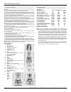
Installation
NOTICE: Re-torque fasteners prior to use. Refer to torque requirements listed in
maintenance manual and attached to pump.
1. A lube-free, clean, dry, compressed air source (or any nonammable, compressed
gas) is recommended. Use a lter that is capable of ltering out
particles larger than 50 microns.
2. All pumps should be mounted in an upright position with the exception of the 1/4”
models which may be rotated 360° to suit the application.
3. When particles exceed the maximum particle specication of the pump or are
sharp enough to cut elastomers install a particle uid lter on the uid
suction line.
4. Fluid suctions lines and air exhaust lines should never be smaller than specied
pipe size of pump.
5. Apply PTFE tape to threads upon assembly to prevent leakage.
6. Never use pipe dope on air line connections.
7. Never use collapsible tube on uid inlet.
8. Do not exceed 10 ft-pounds of torque on plastic pipe threads.
9. If changing to a different application reconrm compatibility of uid.
GENERAL MAINTENANCE
1. Check periodically for product or air leakage. Tighten any joint where leakage is
occurring.
2. When pumping hazardous or toxic materials, diaphragms should be replaced at
regularly scheduled intervals based upon pump usage.
3. In freezing temperatures, the pump must be completely drained when idle.
4. When pumping highly abrasive uids reduce discharge ow rate or reduce air
pressure to prolong diaphragm life.
5. If you are pumping a material that will settle or compact the pump must be ushed
before shut down.
Trouble Shooting
AIR IS APPLIED TO PUMP BUT PUMP IS NOT STARTING
1. Clean lters and debris from all uid lines
2. Make sure all valves on uid lines are open.
3. Inspect diaphragms for rupture.
4. Air pressure must not be below 20 psi (1,3 bar)