


FM60-7309 Operator’s Manual
Page 14 888-249-4855 • www.ZebraSkimmers.com • Zebra Skimmers Corporation
FM60-7309 Operator’s Manual
888-249-4855 • www.ZebraSkimmers.com • Zebra Skimmers Corporation Page 15
PUMP IS PUMPING BUT NOT PRIMING
1. Check all suction line connections for leakage.
2. Inspect check valves for wear or debris.
3. Suction lift specications may be exceeded.
4. If uid is viscous use larger suction lines.
LEAKAGE
1. Retorque all fasteners to specied torque requirements.
2. Replace o-rings.
3. Inspect diaphragms for rupture
LOW FLOW RATE
1. Conrm air pressure and air capacity at the air valve as required.
2. Check for leaks in suction line or obstructions in lines.
3. If uid is viscous use larger suction lines.
4. Viscosity of uid may have increased if temperature is lower.
AIR IN DISCHARGE LINES
1. Check for leaks in suction lines.
2. Inspect diaphragms for rupture.
ERRATIC CYCLING
1. Inspect check valve seats for debris.
2. Inspect uid lines for debris.
3. Automatic valves must be properly functioning.
4. Viscosity of product may be changing.
PREMATURE DESTRUCTION OF WETTED COMPONENTS
1. If uid is abrasive slow down pump or increase size of pump
2. Filter uid for sharp objects.
3. Make sure uid is compatible with wetted materials.
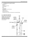
1⁄2˝ MODELS
MAINTENANCE MANUAL
Check Valve And O-ring Maintenance
1. Flush and neutralize the pump to be certain all corrosives or hazardous materials
are removed prior to any maintenance. This procedure should always be followed
when returning pumps for factory service also.
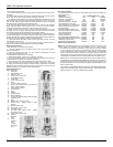
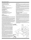
2. Remove the nuts (19) and washers (10) from the four long pumping cap screws
(35). Suction check valve seats and check balls (26, 27) are located inside of the
bottom of the outer chamber (28). Gently remove and inspect for excessive wear,
pitting or other signs of degradation. Inspect valve seat o-rings (38). Replace if
necessary. Discharge check valves are located inside of the bottom of the discharge
elbows (28). Repeat procedure for inspection of discharge check valves.
3. To inspect the manifold o-rings remove the eight sets of nuts, washers and bolts
(10, 19, 20) from each manifold assembly and replace if necessary. Then reassemble,
lightly tighten fasteners. Tighten all external fasteners to nal torque requirement after
pump is completely assembled. The check ball should t into the curved portion of the
valve seat and be facing upward when reinserted into the valve seat location.
NOTE: When using pumps built with PTFE o-rings always replace with new PTFE
o-rings, since the original o-rings will not reseal the pump.
Diaphragm And Pilot Sleeve Assembly Maintenance
4. To inspect diaphragms remove the band clamps (16) from the
outer pumping chambers (28). If replacement is necessary due to
abrasion or rupture unscrew the outer diaphragm plates (29). Models
that are built with PTFE elastomers will have a PTFE overlay (30) that
faces the outer pumping chamber and a back-up diaphragm (31) on
the air side of pump. Pumps without PTFE will contain only the back-
up diaphragms.
5. If there has been a diaphragm rupture and corrosive or viscous
uid has entered the air side of pump the complete air system should
be inspected. After removing diaphragms and inner diaphragm plate
(33), the pilot sleeve assembly (14, 40, 42, 45-47) and diaphragm
rod assembly (13, 15) may be removed by removing the retaining
plates (41) (you may only need to remove one retaining plate) and
pushing the entire unit out through the bore in the intermediate (34).
Diaphragm rod assembly must be unscrewed to remove pilot sleeve.
NOTE: To aid in reassembly use a non-synthetic, petroleum based
lubricating grease without EP additives. Carleton-Stuart MagnaLube
G is recommended.
6. Clean or replace any components that have excessive wear,
dirt build-up, or chemical attack. Lube all components prior to
reassembling. Reassemble pilot sleeve spacers, o-rings and lip seals
(40) within bore of intermediate. Make sure that the open side of the
lip seals is facing outward toward the diaphragms. Also make sure
that the end pilot spacers (14) are at the end on either side of the pilot
sleeve assembly and all inner spacers (47) are separated by o-rings.
Next carefully insert the diaphragm rod assembly with pilot sleeve
inside the assembly in the bore. Reattach retaining plates. Do not
overtighten self-tapping screws (24).
7. Take one diaphragm and invert (reverse the natural bow of the
material) and with the curved side of the inner diaphragm plate facing
the diaphragm assemble onto outer diaphragm plate stud and then
screw assembly into diaphragm rod. Push diaphragm rod to opposite
side of intermediate and add the opposite diaphragm assembly.
Tighten the outer diaphragm plates to 70 in-lbs (7,91 NM) of torque.
NOTE: Inverting the rst diaphragm aids reassembly.
8. Position outer diaphragm chambers onto intermediate making sure that witness
lines are matching.
NOTE: If air valve has been removed, proper orientation of air system with uid
chambers must be observed. The top of the intermediate has a single vertical air
passage slot on the air valve mounting face while the outer chamber check ball cavity
should be pointing downward.
9. When positioning band clamps use soapy water or a compatible lubricating spray
on the inside of band clamps to aid assembly. Tap with a mallet on the outside of
clamp to help position the clamp while tightening the fasteners. The band clamp
fasteners are stainless steel. To prevent galling always apply an anti-seize compound
to the thread. Tighten all external fasteners to nal torque requirement after pump is
completely assembled.
10. Position the reassembled manifolds making sure of the proper orientation in
relation to the air valve for your application. Also make sure that the valve seat o-rings
do not shift from their grooves during reassembly. Flat washers should be placed
under the head of each cap screw and nut. Tighten all external fasteners to nal
torque requirement after pump is completely assembled.
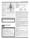
External Fastener Torque Requirements
NOTE: When reassembling loosely tighten all external fasteners adjusting and
aligning and gradually, in an alternating fashion, tighten to torque requirements listed
below.
AIR VALVE CAP SCREWS 40 in-lbs (4,52 NM)
BAND CLAMPS 13.3 ft-lbs (18,08 NM)
MANIFOLD BOLTS, 20 in-lbs (2,26 NM)
OUTER CHAMBER CAP SCREWS, 28 in-oz (0,02 NM) (Plastic Pumps)
OUTER CHAMBER CAP SCREWS, 30 in-lbs (3,39 NM) (Metal Pumps)
Air Valve Maintenance
11. To evaluate air valve components, remove the four cap screws (11), washers,
(25, 10) and nuts from the air valve body (7). The valve plate (5) and shuttle (6) may
be inspected by removing them from their location in the slot in the back of the air
valve. Inspect for scratches or surface irregularities. Replace if necessary. To remove
the plug (1) at the bottom of the air valve, point the bottom of the air valve safely away
from people, direct compressed air through one of the lower holes in the back of the
air valve body and the plug will shoot out. Next push the air valve spool (2) out of the
air valve body. Gently reach in and pull lip seals (43) out of inside bore of the air valve
body. Check for cracks, splitting or scratches. Clean components if replacement is
not necessary. Inspect plug oring (44) for any damage and replace if necessary and
reinsert in o-ring groove.
NOTE: Make sure that the open side of the two lip seals face each other when
reassembling air valve. Lube all components with suggested maintenance grease as
an aid in reassembly.
12. Reinsert air valve spool inside of air valve body. Place shuttle on middle rib of
air valve spool through the square slot in back of air valve. If using original valve
plate lubricate side of plate that was facing the shuttle (or if new valve plate is used
lubricate the lapped and polished side of plate) and place the lubricated side next to
the shuttle in the slot. Press valve plug into air valve body, chamfered end rst.
13. Check that gaskets (3, 4) are not cracked. If damaged replace.
14. After gaskets are pressed back into position align air valve onto intermediate and
reinsert the four capscrews with lock washer and at washers. Apply 40 in-lbs (4,52
NM) of torque to fasteners.