


5-29
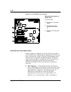
Upgrades and Options
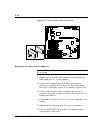
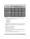
Table 5-1. Option Board Hardware Configurations
OPTION BOARD IRQ
3
MEMORY
ADDRESS
I/O
ADDRESS
OPTION
SLOT
SMC8416BTA (1st)
4
Set by BIOS Set by BIOS Set by BIOS EISA Slot J3
SMC8416BTA (2nd)
4
Set by BIOS Set by BIOS Set by BIOS EISA Slot J4
DigiBoard (1st) Not Required D0000 200 EISA Slot J5
DigiBoard (2nd) Not Required D0000 220 EISA Slot J6
SMC 8432BTA (1st)
4
Set by BIOS Set by BIOS Set by BIOS PCI Slot J9
SMC 8432BTA (2nd)
4
Set by BIOS Set by BIOS Set by BIOS PCI Slot J10
SMC 8434BT (1st)
4
Set by BIOS Set by BIOS Set by BIOS PCI Slot J9
SMC 8434BT (2nd)
4
Set by BIOS Set by BIOS Set by BIOS PCI Slot J10
SMC 9332BDT (1st)
4
Set by BIOS Set by BIOS Set by BIOS PCI Slot J9
SMC 9332BDT (2nd)
4
Set by BIOS Set by BIOS Set by BIOS PCI Slot J10
Adaptec 2940UW
1
Set by BIOS Set by BIOS Set by BIOS PCI Slot J11
5
Mylex DAC960PDU Set by BIOS Set by BIOS Set by BIOS PCI Slot J11
Onboard 7880 SCSI Set by BIOS Set by BIOS Set by BIOS N/A
2
Onboard 7860 SCSI Set by BIOS Set by BIOS Set by BIOS N/A
2
1. When more than 1 SCSI controller is plugged in, use IRQ 14 for secondary controller (non-booting
controller).
2. For disk controllers plugged into slots and the onboard disk controllers, the sequence for BIOS
scanning to determine the primary (Boot) disk controller is:
EISA slots J3 through J6
PCI slot J11
Onboard 7880 SCSI
PCI slots J10 through J8
Onboard 7860 SCSI
PCI slot J7.
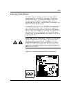
It is recommended that the BIOS be disabled on all SCSI controllers except for the controller with the
boot disk drive attached (see The SCSISelect Utilities in the Configuring Your System chapter. This
saves memory address resources and provides control over the boot device independent of board
slot locations.
3. Additional IRQ’s can be made available as follows:
Disabling Comm Port 1 = IRQ4 is available
Disabling Comm Port 2 = IRQ3 is available
Disabling Parallel Port = IRQ7 is available.
4.
A maximum of three LAN channels consisting of any combination of single or dual channel. Install
EISA LAN card in the first available EISA slot from the bottom. Install PCI LAN card in the first
available PCI slot from the top.
5.
A maximum of two SCSI controllers may be installed. Install the first controller card in the top PCI
slot and the second controller in the second from the top PCI slot.