


2-11
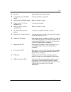
Features
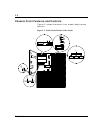
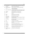
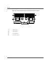
A AC input power
connector
One at the top of the power supply cage that supplies AC
power for all the power supplies.
B Power supplies (two
shown)
Possible configurations, installed from left most bay:
1 supply (nonredundant)
2 supplies (one redundant)
C Security padlock loops One on each side at the top rear of the chassis, one on the
power supply cage, and one on each power supply module..
D Keyboard PS/2-compatible 6-pin mini-DIN connector.
E Mouse PS/2-compatible 6-pin mini-DIN connector.
F — Reserved
G COM2 COM2 serial port 9-pin connector.
H COM1 COM1 serial port 9-pin connector.
I External-SCSI Narrow-SCSI 50-pin connector
J Function select
switches
See Configuring Switch and Jumper Settings in Chapter 4
of this User’s Guide.
K Dump button See Configuring Switch and Jumper Settings in Chapter 4
of this User’s Guide.
L VGA VGA monitor 15-pin connector.
M Printer LPT1 25-pin Centronics-compatible parallel port
connector.
N PCI slots Four PCI add-in board slot locations.
O Knockouts Available to route SCSI signals to peripheral boxes.
P PCI/EISA slot One PCI or EISA add-in board slot location.
Q Knockouts Available to route SCSI signals to peripheral boxes.
R EISA slots Three EISA add-in board slot locations.
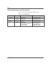
S Power supply status
lamps
See Table 2-4 for status descriptions.