


ZXLD1362EV3 User Guide issue 1 4/7 11-01-2008
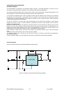
ZXLD1362 Operation
In normal operation, when voltage is applied at +VIN, the ZXLD1362 internal NDMOS switch is turned on. Current
starts to flow through sense resistor R1, inductor L1, and the LEDs. The current ramps up linearly, and the ramp rate
is determined by the input voltage +VIN and the inductor L1. This rising current produces a voltage ramp across R1.
The internal circuit of the ZXLD1362 senses the voltage across R1 and applies a proportional voltage to the input of
the internal comparator. When this voltage reaches an internally set upper threshold, the NDMOS switch is turned off.
The inductor current continues to flow through R1, L1, the LEDs, the Schottky diode D1, and back to the supply rail,
but it decays, with the rate of decay determined by the forward voltage drop of the LEDs and the Schottky diode. This
decaying current produces a falling voltage at R1, which is sensed by the ZXLD1362. A voltage proportional to the
sense voltage across R1 is applied at the input of the internal comparator. When this voltage falls to the internally set
lower threshold, the NDMOS switch is turned on again. This switch-on-and-off cycle continues to provide an average
current (set by the sense resistor R1) to the LEDs, . Please refer to the datasheet [1] for the threshold limits,
ZXLD1362 internal circuits, electrical characteristics and parameters.
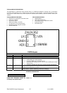
ZXLD1362EV1 Evaluation Board - BOM
Ref Value Package Part Number Manufacturer Notes
R1 0.15R 0805 CRL1220 R15TD Tyco 5%, 200ppm
R2 1k 0805 Generic - -
C1 10uF 100V SMD NACEW100M1006.3x8TR13F NIC Electrolytic - 20%
C2,C4 100nF, 100V 0805 NMC0805X7R104K100TRPLPF NIC 20%
C3 100nF 1206 NMC1206X7R104K100TRPLP3KF NIC
L1 68uH - NPIS24H680MTRF NIC 68uH/1.5A rms
D1 100V, 3A SMC 30BQ100PBF IR Schottky diode
U1 ZXLD1362 TSOT23-5 ZXLD1362E5TA Zetex DC-DC converter
The aluminium PCB guarantees a good thermal dissipation for the ZXLD1362 device, which can produce up to 1 watt
of heat under maximum load conditions. Other sources of heat are the Schottky diode, the inductor and the sense
resistor. Care must be taken in their placement.
Warning: At 60V operation with 700mA output, the board temperature rises by around 50C from ambient
after 30 minutes of operation.
Figure 3: Component layout and circuit board view