


ZXLD1362EV3 User Guide issue 1 5/7 11-01-2008
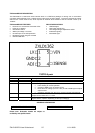
ZXLD1362EV3 Connection Point Definition
Name Description
+VIN Positive supply voltage.
GND
Supply Ground (0V).
ADJ Internal voltage ref. pin (1.25V). This pin can be used to achieve dimming and soft-start,
and for switching the output current off.
• Leave floating for normal operation.
• See 'Circuit Features' section to achieve dimming, soft-start and for switching the
output current off.
LED A LED A connects to the external LED anode
LED K LED K connects to the external LED cathode
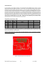
ZXDL1362EV3 Basic operation at full voltage
1. Connect external LEDs across test pins ‘LED A’ (anode) and ‘LED K’ (cathode). The number of external
LEDs that can be connected depends on their operating power and forward voltage drop, but typically 16 x
3.4V LEDs can be connected using a 60V rail. For an external load other than LEDs, the positive terminal of
the load should be connected the anode and the negative to the cathode.
2. Connect VIN and GND.
Warning: The board does not feature reverse battery/supply protection.
3. Set the PSU to the desired input voltage (usually between 30V and 60V)
4. Turn on the PSU. The external LEDs will illuminate and the current should be approximately 700mA.
Warning: Do not stare at the LEDs directly.
Circuit features
N.B. Remove power whilst changing components!
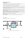
Soft-start
1. The evaluation board is fitted with capacitor C2, which performs the soft start function by slowing the rise
time of the adjust pin at start-up. The pin output impedance is 50K so CxR is the time constant to reach 66%
of output current.
PWM
1. Remove the soft start capacitor C2
2. Refer to the datasheet for how to perform PWM
Switching off the output current
3. Shorting the ADJ pin to GND will cause the LED current to go to zero. Releasing this pin will switch on the
system (creating a soft-start power up sequence if the C2 capacitor is used).
Changing the LED current
1. Remove R1
2. Calculate and fit a new sense resistor, R1, the value of which is based on the required LED current without
dimming. R1 can be calculated using following equation :
R1 = 0.1(V / I
OUT
) where I
OUT
= the LED current.
R1 = the sense resistor value in ohms.
0.1V is the nominal sense voltage with ADJ open circuit or set to 1.25V.