Appendix E: 1701 Wafer Reader Installation Options In-Sight
®
1700 Series Wafer Reader
116
Table E-1 shows examples of the 1701 reader’s vertical working distances and the
corresponding horizontal working distances required if no focal adjustment is made.
Table E-1: Working Distances
VERTICAL WORKING DISTANCE (MM)
CORRESPONDING HORIZONTAL
WORKING DISTANCE (MM)
5.0 N/A
10.0
*
N/A
15.0 N/A
20.0 N/A
25.0 1.1
30.0 6.1
40.0 16.1
50.0
*
26.1
60.0 36.1
70.0 46.1
80.0 56.1
* Indicates factory-set working distances
Adjusting the Focus on the 1701
The recommended working distance range is 1 to 80 mm for the 1701 reader in the
vertical position. If using the horizontal mirror mount, the recommended working distance
range is 1 to 56.1 mm.
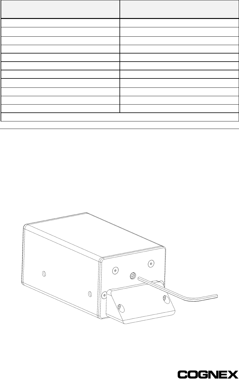
Once the working distance is established, the focus can be adjusted using the focus
adjustment screw (M3 hex screw), located in the center of the 1701 reader’s front face
plate (see Figure E-0-3). To adjust the focus, use a 2.5 mm Allen wrench. Turn the focus
adjustment screw clock-wise if the reader is moved closer to the wafer; turn the screw
counter clock-wise if the reader is moved farther away from the wafer.
Figure E-0-3: Location of Focus Adjustment Screw


