40 41
If using HI 504 the fail safe resistors are already connected
on it, so they are necessary only if the HI 504910 transmitter
is connected to a PC.
The interface signals are optoisolated from the ground of the
instrument, the electrode and the temperature sensor.
Before connecting the meter to the computer, consult the com-
puter manual.
The instrument can only work as a slave component. In other
words it can work as a remote terminal equipment answering
to the commands only.
RS485 PROTOCOL
This section is useful when connecting the HI 504910 trans-
mitter to a computer workstation or PLC, and an user-software
is used instead of HI 92500.
Commands are composed of four parts: addresses, com-
mand identifier, parameter, end of command.
Some of the commands are used when the master is request-
ing information from the controller, other when the master
wants to set a parameter in the instrument memory (RAM or
EEPROM).
The end of commands corresponds to the CR char (0x0d).
The master software must send the command string with a
maximum delay of 20 ms between each character.
The program on the master must not allow setting commands
other than keyboard commands if the general password has
not been entered. After the general password recognition
through the “PWD” command, a 1-minute time-out is let
before the instrument locks again, i.e. if the PC program
waits for more than 1 minute between two subsequent setting
commands, the second one is not fulfilled and the “PWD”
command must be issued again.
CONNECTIONS
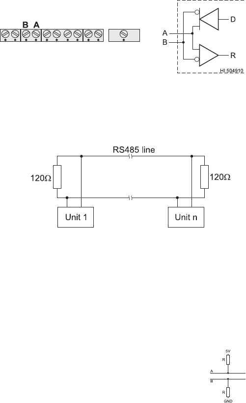
The connections for the 2-pin RS485 terminal provided are
as follows:
The instrument has no internal line termination. To terminate
the line, an external resistor equal to the characteristic line
impedance (typically 120Ω) must be added at both ends of
the line.
The RS485 can connect up to 31 Digital Transmitters on the
same physical network. All the units are slave devices and
are monitored and controlled by a single master station (typi-
cally an industrial PLC or PC).
Each unit is identified by its RS485 address, included in the
00 to 99 interval, which corresponds to the Instrument ID
configured through the setup item G.11.
(If the instrument does not recognize the address within the
command string, then it discards all the following bytes).
To avoid erroneous readings in Open-Line
conditions, pull-up and pull-down resis-
tors should be connected as shown (Fail
Safe Open Line protection method).
The Fail-Safe resistors are connected only to one unit in the
line, and their value depends on the application and char-
acteristic impedance of the connection cable.
