24
MZ-N707
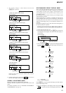
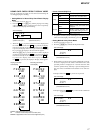
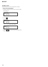
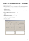
TEMPERATURE CORRECTION
• Adjustment Method of Temperature Correction
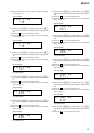
1. Select the manual mode of test mode, and set the item number
015 (see page 14).
2. Measure the ambient temperature.
3. Adjust with [VOL +], [VOL --] key so that the adjusted value
(hexadecimal value) becomes the ambient temperature.
(Initial value: 19h = 25 °C, Adjusting range: 80h to 7fh (–128
°C to +127 °C)
4. Press the X key to write the adjusted value.
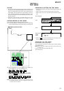
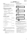
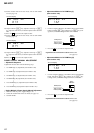
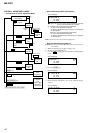
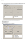
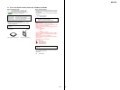
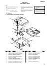
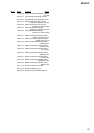
LASER POWER CHECK
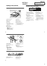
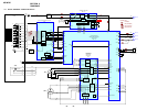
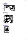
• Connection
• Checking Method
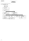
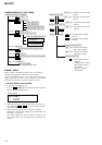
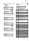
1. Select the manual mode of test mode (see page 14), and set
the laser power adjusting mode (item number 010).
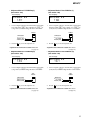
2. Press the
. key continuously until the optical pick-up
moves to the most inward track.
3. Open the cover and set the laser power meter on the objective
lens of the optical pick-up.
4. Press the N key, and set the laser MO read adjustment mode
(item number 011).
5. Check that the laser power meter reading is 0.81 ± 0.08 mW.
6. Check that the voltage both ends (TP (+) and TP (–)) of resis-
tor R521 at this time is below 44 mV.
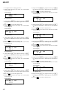
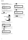
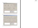
7. Press the
N key, and set the laser CD read adjustment mode
(item number 012).
8. Check that the laser power meter reading is 0.97 ± 0.10 mW.
9. Check that the voltage both ends (TP (+) and TP (–)) of resis-
tor R521 at this time is below 44 mV.
10. Press the N key, and set the laser MO write adjustment mode
(item number 013).
11. Check that the laser power meter reading is 4.95 ± 0.50 mW.
12. Check that the voltage both ends (TP (+) and TP (–)) of resis-
tor R521 at this time is below 80 mV.
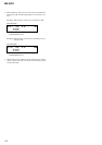
13. Press the x/CHG key to quit the manual mode, and activate
the test mode (display check mode).
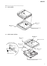
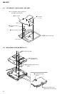
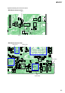
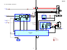
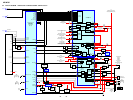
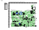
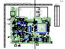
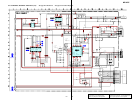
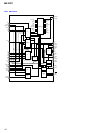
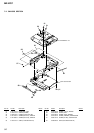
Checking and Connection Location: MAIN board
(see page 25)
digital voltmeter
MAIN board
laser
power meter
Optical pick-up
objective lens
TP (+)
TP (–)
Laser
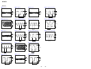
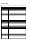
0 10
Set LCD display
LrefPw **
0 11
Set LCD display
HrefPw **
0 12
Set LCD display
SetTmp **
0 15
**
: Adjusted value
Set LCD display
WritPw **
0 13
Set LCD display