19
MZ-NF810/NF810CK
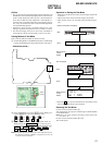
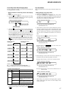
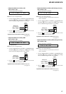
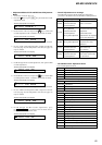
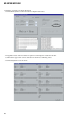
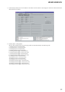
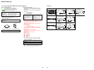
• Adjustment Method of VC2_HIGH
(item number: 744)
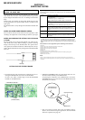
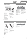
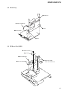
1. Connect a digital voltmeter to the TP1905 (VCOUT) on the
MAIN board, and adjust
[VOL +] key (voltage up) or [VOL --]
key (voltage down) so that the voltage becomes 2.55 ± 0.01V.
2. Press the
X key on the set or the key on the remote
commander to write the adjusted value.
Adjustment and Connection Location:MAIN board
(see page 22)
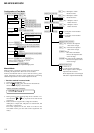
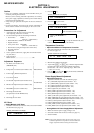
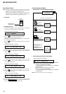
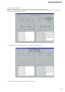
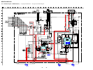
• Adjustment Method of REG1
(item number: 745)
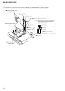
1. Connect a digital voltmeter to the TP1909 (REGO1) on the
MAIN board, and adjust [VOL +] key (voltage up) or [VOL --]
key (voltage down) so that the voltage becomes 2.05 ± 0.01V.
2. Press the X key on the set or the key on the remote
commander to write the adjusted value.
Adjustment and Connection Location:MAIN board
(see page 22)
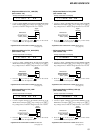
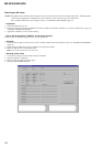
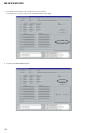
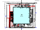
• Adjustment Method of REG3_LOW1 (H)
(item number: 747)
1. Connect a digital voltmeter to the TP1907 (REGO3) on the
MAIN board, and adjust
[VOL +] key (voltage up) or [VOL --]
key (voltage down) so that the voltage becomes 1.25 ± 0.01V.
2. Press the X key on the set or the key on the remote
commander to write the adjusted value.
Adjustment and Connection Location:MAIN board
(see page 22)
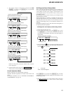
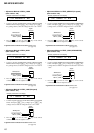
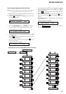
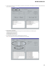
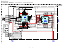
• Adjustment Method of VC1_LOW (PB)
(item number: 741)
1. Connect a digital voltmeter to the TP1928 (VCO1) on the MAIN
board, and adjust
[VOL +] key (voltage up) or [VOL --] key (volt-
age down) so that the voltage becomes 2.35 ± 0.05V.
2. Press the
X key on the set or the key on the remote
commander to write the adjusted value.
Adjustment and Connection Location:MAIN board
(see page 22)
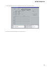
• Adjustment Method of VC1_HIGH (REC)
(item number: 742)
1. Connect a digital voltmeter to the TP1928 (VCO1) on the
MAIN board, and adjust [VOL +] key (voltage up) or [VOL --]
key (voltage down) so that the voltage becomes 2.75 ± 0.05V.
2. Press the X key on the set or the key on the remote
commander to write the adjusted value.
Adjustment and Connection Location:MAIN board
(see page 22)
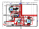
• Adjustment Method of VC2_LOW
(item number: 743)
1. Connect a digital voltmeter to the TP1905 (VCOUT) on the
MAIN board, and adjust
[VOL +] key (voltage up) or [VOL --]
key (voltage down) so that the voltage becomes 2.30 ± 0.01V.
2. Press the X key on the set or the key on the remote
commander to write the adjusted value.
Adjustment and Connection Location:MAIN board
(see page 22)
digital
voltmete
MAIN board
TP1928 (VCO1)
BATT– (GND)
digital
voltmete
TP1905 (VCOUT)
BATT– (GND)
MAIN board
digital
voltmete
MAIN board
TP1928 (VCO1)
BATT– (GND)
digital
voltmete
TP1905 (VCOUT)
BATT– (GND)
MAIN board
digital
voltmete
TP1909 (REGO1)
BATT– (GND)
MAIN board
digital
voltmete
TP1907 (REGO3)
BATT– (GND)
MAIN board
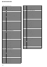
741 VC1 L **
**
: Adjusted value
Remote commander LCD display
742 VC1 H **
**
: Adjusted value
Remote commander LCD display
743 VC2 Lo **
**
: Adjusted value
Remote commander LCD display
744 VC2 Hi **
**
: Adjusted value
Remote commander LCD display
745 REG1 **
**
: Adjusted value
Remote commander LCD display
747 REG3L1 **
**
: Adjusted value
Remote commander LCD display