4
1. Features (continued)
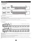
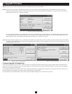
1.5 External Views
1.5.1 Front View
1.5.2 Rear View
LIVE
BANK
SELECTED
12345678
8-PORT KVM SWITCH
MODEL: B042-008
LIVE
12 34 56 78 910111213141516
BANK
SELECTED
16-PORT KVM SWITCH
MODEL: B042-016
Figure 1-1: B042-008 Front Panel
Figure 1-3: B042-008 Rear Panel
Figure 1-2: B042-016 Front Panel
Figure 1-4: B042-016 Rear Panel
Port-Switching Buttons
Use these buttons to switch directly to the desired port.
Numerical LED Displays and Indicators
Bank LED Display: Shows the currently selected KVM in a daisy-chain. The LED will default to bank 1 if the KVM is not daisy-chained to other KVMs.
Red ‘Live’ LED Indicators: A Red LED will be displayed above each port with a connected computer that is running power through the PS/2 or USB
console interface. If the connected computer is powered off, the red LED will not be illuminated.
Green ‘Selected’ LED Indicators: A Green LED will be displayed above the computer port which is currently selected as active.
Power Receptacle: The power receptacle should receive electricity from the included 9V DC 1A power adapter cord. Its center pin is of a positive polarity.
Console Ports: The console ports provide keyboard and mouse connectors for both PS/2 and USB interfaces, as well as a HD15 (F) connector for the
monitor/LCD display.
PC Port: The PC port is a HD15 (F) connector integrated with USB and PS/2 keyboard, mouse and video. To connect a computer to the PC port, you
will need one of Tripp Lite’s P780-Series USB PS/2 KVM Cable Kits. Not included.
Daisy-Chain IN Port: The daisy-chain IN port is a HD15 (M) connector which provides daisy-chaining upstream to a B042-Series KVM Switch.
The daisy-chain IN port is also used in the firmware upgrade process.
Daisy-Chain OUT Port: The daisy-chain OUT port is a HD15 (F) connector which provides daisy-chaining downstream to a B042-Series KVM Switch.
1
1
1
2
2
2
234
4
4
4
5
3
3
3
1
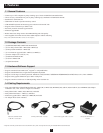
NetController™ 8-Port KVM Switch Model: B042-008
NetController™ 16-Port KVM Switch Model: B042-016
1
1
3
34 2
5
5
4 2