


14 C
HAPTER
1: I
NTRODUCING
THE
S
WITCH
1100
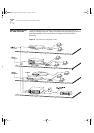
LEDs
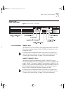
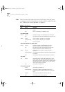
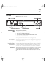
Table 3 lists the LEDs visible on the front of the Switch, and their states
according to color. For information on using the LEDs for problem solving,
see “Checking for Correct Operation” on page 30.
Table 3
LED behavior
LED Color Indicates
TCVR Yellow Port 1 is a Transceiver Module fitted to the rear of the
Switch.
Off Port 1 is operating as a 10BASE-T port.
Port Status LEDs
Packet Yellow Packets are being transmitted/received on the port.
Off No packets are being transmitted/received on the port.
Status Green A link is present, and the port is enabled.
Green flashing A link is present, but the port is disabled.
Off No link is present.
Expansion Module Port Status LEDs
Packet Yellow Packets are being transmitted/received on the
Expansion Module or Matrix Module port(s).
Off No packets are being transmitted/received on the
Expansion Module or Matrix Module port(s).
Status Yellow A valid Expansion Module or Matrix Module is
installed.
Yellow flashing An unrecognized Expansion Module or Matrix Module
is installed.
Off No Expansion Module or Matrix Module is installed.
Unit LEDs
1–8 Green The Switch forms a stack with other Switch 1100 /
Switch 3300 units; the LED indicates the position of
the Switch in the stack and that a link is present. Note
that although there are eight LEDs, only four Switch
units can be stacked at present.
Off The Switch is stand-alone.
Power/Self Test LED
Green The Switch is powered-up.
Green flashing The Switch is either downloading software or is
initializing (which includes running a Power On Self
Test).
Yellow The Switch has failed its Power On Self Test.
Off The Switch is not receiving power.
16950ua.bk Page 14 Thursday, August 27, 1998 11:55 AM