


Choosing the Correct Cables 29
CAUTION: If you want to install the Switch using a Category 5E or
Category 6 cable, 3Com recommends that you briefly connect the cable
to a grounded port before connecting network equipment. If you do not,
the cable’s Electrostatic Discharge (ESD) may damage the Switch's port.
You can create a grounded port by connecting all wires at one end of a
UTP cable to an earth ground point, and the other end to a female RJ-45
connector located, for example, on a Switch rack or patch panel. The
RJ-45 connector is now a grounded port.
3Com recommends that you use Category 5 twisted pair cable—the
maximum segment length for this type of cable is 100 m (328 ft).
Choosing the Correct
Cables for the
Switch 4200G
All of the ports on the front of the Switch 4200G 28-Port are
100BASE-FX MT-RJ multi-mode ports. The MT-RJ port is a small form
factor fiber-optic port with the transmit and receive fibers in the same
cable. Unlike many fiber-optic systems, only one MT-RJ cable is needed to
connect two MT-RJ ports together.
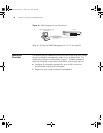
To connect a front panel port to another 100BASE-FX MT-RJ multi-mode
port, or to a patch panel, a single MT-RJ multi-mode pinless jumper cable
is required. Since standard MT-RJ cables are cross-over cables, no
Auto-MDIX sensing is required. The maximum cable length is 2 kilometers
(1.24 miles).
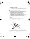
CAUTION: Do not connect pinned MT-RJ connectors into any port on the
Switch 4200G as this may damage the unit. The ports have locator pins
fitted and are designed for standard (pinless) connectors.
To connect a front panel port to a 100BASE-FX single mode port, or to a
port that does not have an MT-RJ connector, an adaptor will be required.
It is not possible to connect a front panel port to a 1000BASE-FX port.
10014914AA.book Page 29 Friday, July 7, 2006 2:08 PM