


32 CHAPTER 2: INSTALLING THE SWITCH
WARNING: Ensure that the circuit breaker in the RPS is in the open (off)
position when connecting the cable to the RPS and the cable and
connector to the Switch.
WARNING: You must ensure that the positive terminal on the Switch is
connected to the positive (common) terminal of the RPS and that the
negative terminal on the Switch is connected to the negative (circuit
breaker) terminal of the RPS.
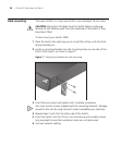
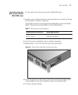
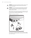
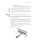
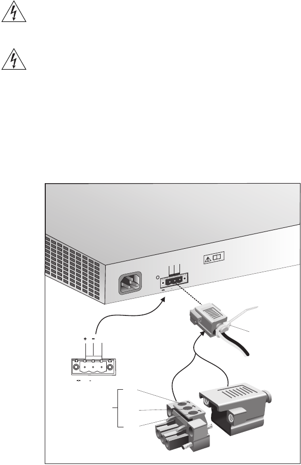
Figure 9 shows how to connect the power supply to the RPS socket in the
back of the Switch. Use the cable tie supplied with your Switch to support
the cable at the rear of the RPS connector as shown.
Figure 9 RPS Connection to the Switch
When the RPS is connected to the Switch, the circuit breaker in the RPS
can be moved to the closed (on) position and the Switch will be powered
by the -48V DC power.
+
-
NULL
-48 -60V;2.0A
100-240V;50/60Hz;1.0A
~
NULL
-48 -60V;2 0A
Null
+
-
Pinout
Cable Tie