


10 CHAPTER 2: SYSTEM DESCRIPTION
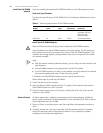
Power Supply Module
Visual indicators
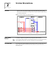
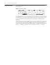
The front panel of the power supply module has three LEDs (Figure 5). Their
descriptions, colors, and functions are shown in Table 2.
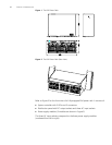
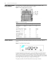
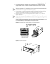
System Controller The PoE Power Rack has a system controller at the front of the chassis. Refer to
Figure 6.
Figure 6 Front Panel of the Controller
To indicate operational and alarm status, a green LED (RUN) and red LED (ALM) are
located on the front panel of the PoE system controller. When the system has an
alarm, such as input failure, input over-voltage or under-voltage, output over-voltage
or under-voltage, power supply failure, or power supply self-protection, the red (ALM)
LED will light. Once the alarm status is cleared, the LED goes off.
The system controller of the PoE Power Rack has two major functions:
Figure 5 Power Supply Module Front Panel
Table 2 LED State Description
Condition AC OK (green) DC OK (green) Fault (Red)
All OK Lighted Lighted Off
Thermal alarm
(Ambient)
Lighted Off Off
Thermal alarm (fan fail) Lighted Off Lighted
Blown AC fuse in unit Lighted Off Lighted
Low or no AC > 15mS
(single unit)
Off Off Off
AC not present in any
power supply module
Off Off Off
Over Voltage Latched
shutdown
Lighted Off Lighted
Any internal failure Lighted Off Lighted