


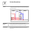

System Controller 11
■ Monitor system operation status - An AC sensor card inside the PoE Power Rack
samples the AC input voltage. The sampled signal is sent to the controller for
processing. If the AC input voltage is lower than the pre-set alarm level, the
controller reports an AC input under-voltage alarm. Likewise, if the input voltage is
higher than the pre-set alarm level, the controller reports an AC input over-voltage
alarm. The DC output voltage is also sampled and sent to the controller. If the
output voltage is lower than the pre-set alarm level, the controller will report a DC
Low alarm. Likewise, if the DC output voltage is higher than the pre-set alarm, the
controller reports a DC output High alarm. The power supply module status
communicates with the controller via an internal RS485 bus. If the power supply
modules issues an alarm, the alarm is passed to the controller. Power supply
module failure alarms include: AC input failure, DC output failure, fan failure, high
output voltage, current limit, over temperature, and module shut-down.
■ Communicate with deamon systems - The controller supports interface to the
Switch 8800 chassis through RS232 or RS485 cable connection. A cable is
provided with the PoE Power Rack for attachment to the Switch 8800 (connect the
RS232 connector end to the PoE Power Rack and connect the RJ45 cable end to
the port labeled "Com" next to the PoE DC terminal block on the back of the
Switch 8800). Using CLI commands, the user can receive and read system
information or command the operation of the PoE Power Rack. The RS485-1 and
RS485-2 have the same function. The customer can choose only one port for
communication. The RS485/RS232 can not work at same time, so do not connect
them both at the same time.
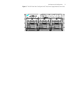
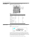
There is one RS485 port and one RS232 interface on the rear panel of the PoE Power
Rack (the cable provided with the PoE Power Rack is a RS232 cable type).
The RS485 and RS232 signals are described in Table 3 and Table 4. :
Table 3 RS485 Pin Definitions
Pin Definition
1 Transmit, +
2 Transmit, -
3 Receive, +
4 Ground
5 Not used
6 Receive, -
7 Ground
8 Not used
Table 4 RS232 Pin Definitions
Pin Definition
1 Not used
2 Receive
3 Transmit
4 Not used
5 Ground
6 - 9 Not used