


4
INSTALLATION AND TESTING
Introduction This section outlines the sequence for installing the PoE Power Rack, including plug-in
modules. Test procedures for verifying the integrity of the installation are also
included.
Guidelines The device must be installed to allow sufficient front and rear access. All cables must
be routed through insulated conduit openings. All service operations can be
completed on the front of the power rack.
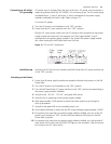
EMI Considerations When running the DC output cables, ensure that the positive and negative cables are
routed so as no loops are created.
Safety WARNING:
■ Only qualified personnel can install and service the PoE Power Rack.
■ Hazardous energy is present in the device and on the interface cables, which can
cause electric shock, serious injury, or death if safety precautions are ignored.
Follow all safety warnings and practices when servicing this equipment.
Installation Sequence Review all safety warnings in Section 3 before beginning the installation process.
Observe all warnings and labels on the equipment.
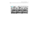
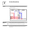
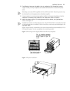
The PoE Power Rack consists of a chassis which includes AC and DC distribution
modules, one system controller, one power supply module and one power supply
module bracket. Refer to
Figure 2 and Figure 3 for relationship of components.
Note that the PoE Power Rack is shipped mostly pre-assembled so as to minimize the
overall installation process. The following installation sequence is recommended:
1 Mount chassis
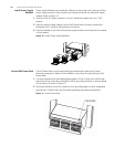
2 Install power supply modules
3 Ground frame
4 Connect to Switch 8800 Chassis
5 Connect to loads
6 Connect to AC utility/AC grounding
7 Initialize the system